Noise preventing device of balance gear of crank

A technology for balancing gears and crankshafts, which is applied in the direction of hoisting devices, portable lifting devices, belts/chains/gears, etc. It can solve the problems of increased manufacturing costs, complicated structures, and inconvenient assembly, so as to improve the use efficiency, simplify assembly, and Reduce the effect of components

Inactive Publication Date: 2007-09-19
KYMCO
View PDF0 Cites 11 Cited by
  • Summary
  • Abstract
  • Description
  • Claims
  • Application Information

AI Technical Summary

Problems solved by technology

[0004] However, as we all know, when the gears are meshing, due to the tolerance of the gears during manufacturing, the two gears cannot be in a fully meshed state, but there will be some gear back lash, so When the driving gear 17 on the crankshaft 13 is driving the balance gear 41 on the balance shaft 4, the two gears are meshing with each other at a high speed, so there will be abnormal sound or even noise
[0005] Please refer to FIG. 3 , the usual way to solve the noise problem between the two gears is to divide the balance gear 41 on the balance shaft 4 into two to form a main gear 411 and a secondary gear 412, which are next to the main gear 41 The pinion gear 412 is sleeved, and the pinion gear 412 can be close to the main gear 412 by a torsion spring 42. One end of the torsion spring 42 is inserted on the pinion gear 412, and the other end of the torsion spring 42 is then inserted into a ring buckle. On the member 43, the annular fastener 43 is pressed on the balance shaft 4 in a tight fit, and is blocked by a positioning pin 44, and the auxiliary gear 412 and the main gear 411 are kept constant by the action of the torsion spring 42. offset, so as to offset the tooth backlash between the driving gear 17 and the main gear 411, and the secondary gear 412 can freely rotate at a small angle on the balance shaft 4, when the driving gear 17 on the crankshaft 13 is driving the balance shaft 4, the driving gear 17 on the crankshaft 13 will first contact the pinion gear 412, and the pinion gear 412 will be driven by the action of the torsion spring 42 to rotate a small angle on the balance shaft 4, When the auxiliary gear 412 rotates a small angle, it can be aligned with the main gear 41. At this time, the driving gear 17 on the crankshaft 13 will drive the main and auxiliary gears 411.412 to rotate together, and then drive the balance shaft 4 to rotate synchronously. The above-mentioned structure can effectively solve the noise problem between the two gears; however, as mentioned above, the usual way to solve the noise problem between the two gears is obviously too complicated, which will cause inconvenience in assembly and cause manufacturing costs. increase, especially the ring fastener 43 is combined with the balance shaft 4 in a tight arrangement, which further causes difficulties in manufacturing

Method used


Image

  • Noise preventing device of balance gear of crank
  • Noise preventing device of balance gear of crank
  • Noise preventing device of balance gear of crank

Examples


Embodiment Construction

[0021] In order to be easier to understand the mechanism of the present invention and the effect that can be achieved, it is described as follows in conjunction with the drawings:

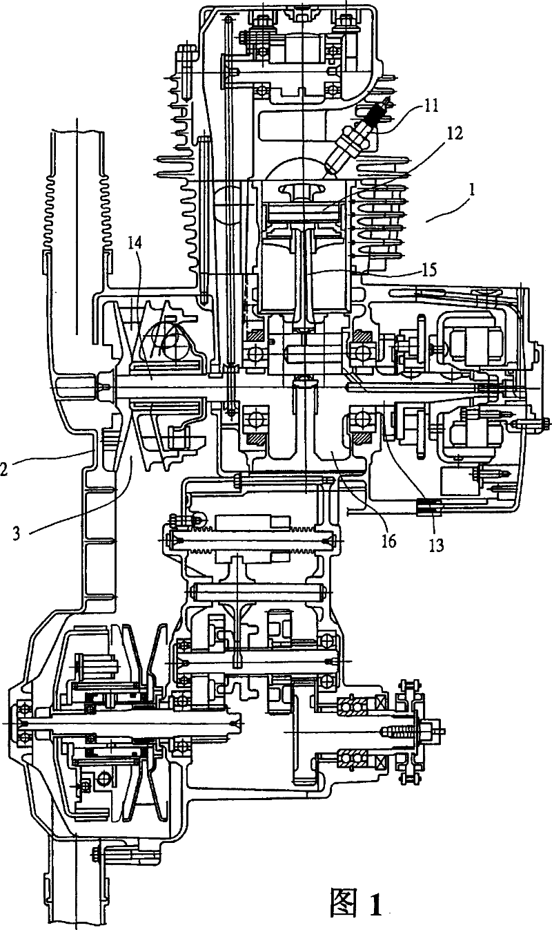
[0022] Its basic structure and mode of operation of the engine of the present invention are all the same as those known in the art, so the following detailed description of the implementation of the present invention will not repeat the relevant engine part, and will be stated first.

[0023] First, please refer to Figs. 4 and 5, the crankshaft 5 of the present invention is connected with the piston 52 through the connecting rod 51, the bottom of the crankshaft 5 has a counterweight 53, and the two sides of the counterweight 53 are respectively sleeved with bearings 54 In addition, a driving gear 55 is arranged between the counterweight 53 and the bearing 54 on one side, and a balance shaft 6 is arranged beside the parallel side of the crankshaft 5 .

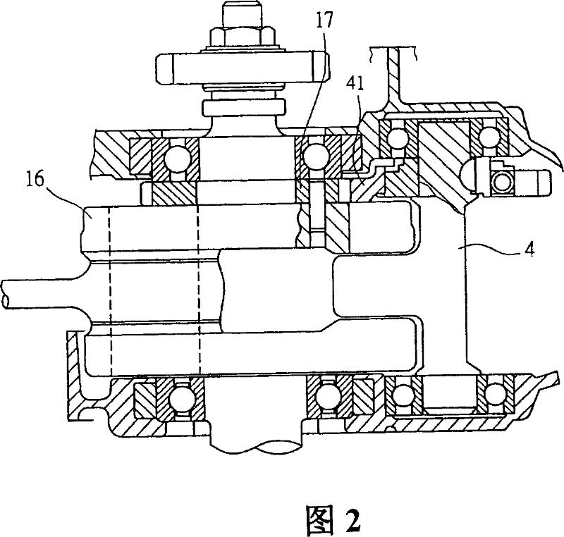
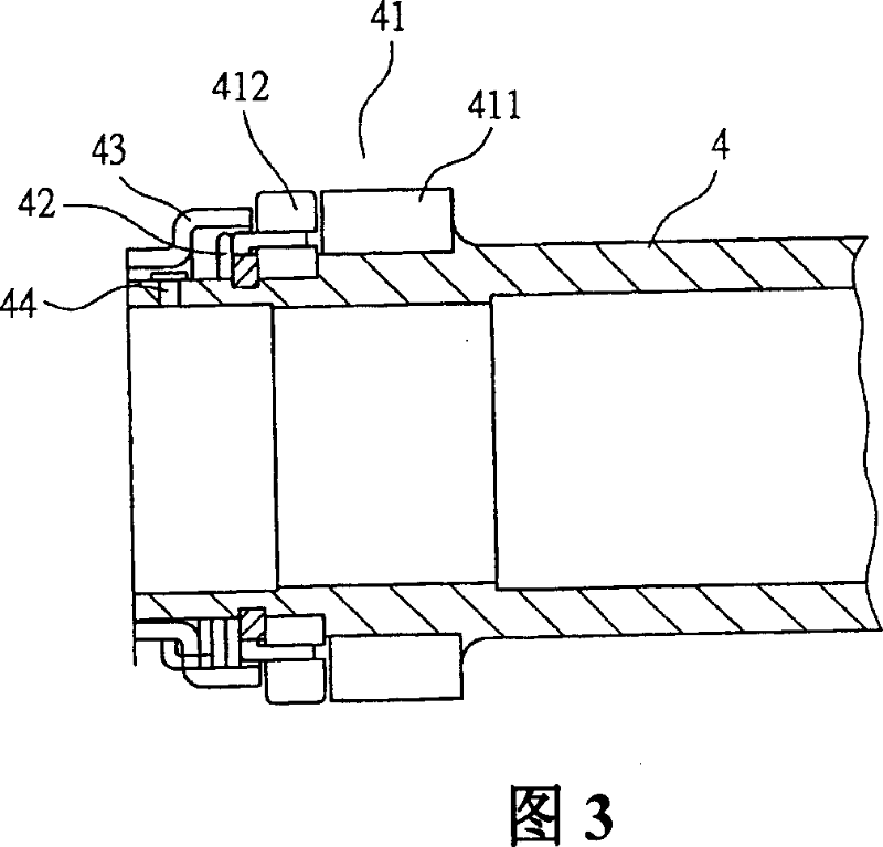
[0024] A balance gear 7 is sheathed on the sid...


PUM


Abstract

The invention relates to a balancing gear noise preventing device of a engine crankshaft, the balancing gear includes a master gear, an auxiliary gear and a torsion spring, which is nested on a balancing shaft, characterized in that the torsion spring is provided between the master gear and the auxiliary gear, the master gear is provided at least a flange seat and a fixing hole, the auxiliary gear is provided at least one through hole, which is fitly nested in the flange seat, thus, the auxiliary gear can be rotating on the flange seat of the master gear. A limitation column is provided inside the through hole of the auxiliary gear, lower part of the limitation column is fixed in the fixing hole of the master gear, offset of the auxiliary gear is limited with a gap kept by the upper part of the limitation column and the through hole of the auxiliary gear. By employing said mechanism, components of the balancing gear noise preventing device can be reduced, and the assemblage is simplified.

Description

【Technical field】 [0001] The invention relates to a noise preventing device for a balance gear of an engine crankshaft. 【Background technique】 [0002] As far as the structure of the engine 1 is concerned, please refer to Fig. 1, it is to establish a transmission box 2 on the side of the engine 1, and a belt speed change mechanism 3 is established in the transmission box 2, after the oil gas mixed with gasoline and air is input into the engine 1 , that is, the ignition device 11 ignites the oil and gas to explode, thereby pushing the piston 12 to reciprocate, and driving the crankshaft 13 connected with it, and the crankshaft 13 stretches into the transmission case 2 with the shaft 14 and is connected with the belt speed change mechanism 3, and through The belt speed change mechanism 3 drives the rotation of the rear wheel, and the rear wheel drives the front wheel to rotate synchronously, so as to achieve the purpose of advancing. [0003] Please refer to Fig. 2 for the ne...

Claims


Application Information

Patent Timeline
Patent Type & Authority Applications(China)
IPC IPC(8): F16H55/18F16F15/24
Inventor 何昭昌
Owner KYMCO
Why Eureka
Try Eureka