Ultra-low frequency underwater acoustic transducer

An underwater acoustic transducer and ultra-low frequency technology, applied in the direction of sound-producing equipment, instruments, etc., can solve problems such as large performance impact, and achieve the effect of improving radiation capacity and realizing ultra-low frequency.

Inactive Publication Date: 2007-09-19
INST OF ACOUSTICS CHINESE ACAD OF SCI
View PDF0 Cites 14 Cited by
  • Summary
  • Abstract
  • Description
  • Claims
  • Application Information

AI Technical Summary

Problems solved by technology

Another disadvantage of moving coil transducers is that th

Method used


Image

  • Ultra-low frequency underwater acoustic transducer
  • Ultra-low frequency underwater acoustic transducer

Examples


Embodiment 1

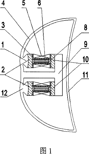
[0026] With reference to Fig. 1, make an ultra-low frequency underwater acoustic transducer of the present invention, the shell of this underwater acoustic transducer is made up of primary curved beam 4, secondary curved beam 11, T-shaped mass yoke 9 and first protrusion 1, All are made of stainless steel. The first-level bending beam 4 and the second-level bending beam 11 form a composite bending beam, whose cross-sectional shape is similar to a "bow" shape, and the bending-tension shell of the composite beam is a translational body with a "bow"-shaped section, and the two ends of the translational body are not closed . The thickness of the T-shaped mass yoke in this embodiment is 40 mm. In this embodiment, the primary bending beam 4 and the secondary bending beam 11 adopt the same wall thickness, which is 15 mm.

[0027] The first protrusion 1 is connected to the primary bending beam 4. The surface of the first protrusion 1 is in the shape of a convex arc. The surface of 2...

Embodiment 2

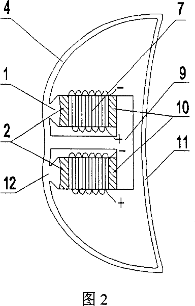
[0034] As shown in FIG. 2 , in this embodiment, a piezoelectric ceramic stack 7 is used as a driving element. The piezoelectric ceramic stack 7 is formed by bonding rectangular piezoelectric ceramic sheets, and the ceramic sheets are connected in parallel in circuit form. The prestressing method of the piezoelectric ceramic stack 7 is the same as that of the first embodiment.

[0035] Other parts of this embodiment are identical to Embodiment 1.


PUM


Abstract

The invention relates to an ultra-low frequency acoustic transducer comprises a first grade bending girder, a second grade bending girder, a first projection, and a second projection, the first and the second projection are provided on an inner wall of the first grade bending girder, a T-shape quality yoke is arranged between the two projections and composes a composite girder bending-opening shell together with the first grade bending girder, a bow-shape closed curved face is composed by the first grade bending girder and the second grade bending girder and has a sturcture of symmetrical upper and lower portions, both two end faces of a translation body are not closed; a driving member, a first transition block and a second transition block compose an inner chamber assembling unit of the transducer, the size of the assembling unit in a length direction is larger than a distance between the projections and the T-shape quality yoke; the first transition block and the second transition block are arranged at two outer side of the driving members of each assembling unit, respectively, at least a driving member and the transition blocks arranged at left and right sides of the driving member are mounted between the first grade bending girder and the T-shape quality yoke. The transducer of the invention has a structure format which is better for realizing an ultra-low frequency and high power radiation.

Description

technical field [0001] The invention belongs to the field of acoustic sensors, in particular, the invention relates to a composite beam ultra-low frequency underwater acoustic transducer composed of two-stage curved beams. Background technique [0002] With the development of modern sonar technology and the continuous expansion of the application field of sonar technology, the low-end operating frequency of sonar has been extended to hundreds of hertz, and even tens of hertz are used in some new fields. Therefore, the development of ultra-low frequency underwater acoustic transducers has highlighted the necessity. [0003] There are many ways to realize the ultra-low frequency radiation of the underwater acoustic transducer. Japan once developed a rare-earth low-frequency high-power ring transducer for marine tomography detection. The resonant frequency is 30Hz. The maximum size of its shape and structure is 2m, and the weight in the air is 5 tons. [0004] Another multipo...

Claims


Application Information

Patent Timeline
IPC IPC(8): G10K9/12
Inventor 刘永平莫喜平
Owner INST OF ACOUSTICS CHINESE ACAD OF SCI
Why Eureka
Try Eureka