Method and device for positioning working position of double power supply switch device circuit breaker
A dual power switching and circuit breaker technology, which is applied in the direction of circuit devices, circuits, emergency power arrangements, etc., can solve the problems of poor electromagnetic compatibility and poor reliability of dual power switching devices, and achieve good adjustability and improved performance.
- Summary
- Abstract
- Description
- Claims
- Application Information
AI Technical Summary
Problems solved by technology
Method used
Image
Examples
Embodiment 1
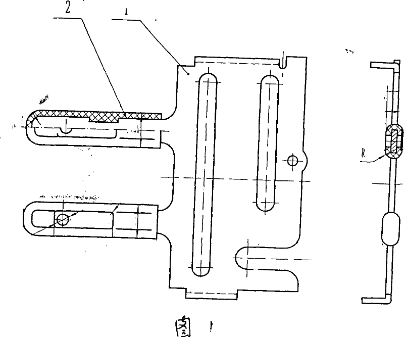
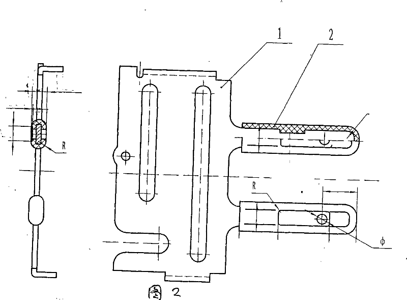
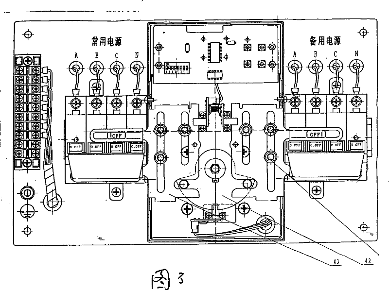
[0012] Embodiment 1 is a typical embodiment, which is explained in conjunction with accompanying drawings 1-3. There are two left and right escapement clips 505, two circuit breaker handles 503, Two photo-interrupters 504, the two escapement clips respectively clamp the respective circuit breaker handles to perform electrical operations of "opening" and "closing" to connect and break the circuit; this embodiment is in the escapement clip Add a light through hole 501 and install a photoelectric interrupter 504 at the position of the escapement clamp light through hole 501 when the circuit breaker performs the electrical operation of "closing"; When the position of the through hole 501 reaches the photoelectric interrupter 504, the photoelectric interrupter outputs an electrical signal to provide the controller with a position signal of the circuit breaker when the light passes through the optical through hole. The controller issues work instructions to the motor of the operatin...
Embodiment 2
[0013] The technical solution of embodiment 2 is improved as follows: the light through holes on each escapement clip are a series of light through holes on the route passing through the photoelectric interrupter. Further provide the controller with the position signal in the movement of the handle of the circuit breaker, so that the speed of the handle movement can be read, so as to detect the running state of the motor and the operating mechanism, which provides the possibility for the controller to judge the failure of the motor and the operating mechanism , and can provide solutions in the early stages of the agency and when the work fails. , the design of optical through holes, optical through hole strings, and gratings in the follow-up improvement scheme provides the possibility for the controller to judge the faults of the motor and the operating mechanism, and can provide solutions when the mechanism is early and the work fails.
Embodiment 3
[0014] The technical solution of embodiment 3 is further improved as follows: each escapement clip has a grating, and when the escapement clip moves, the grating provides the controller with an electric pulse sequence through the photointerrupter, and the controller can judge the movement of the motor and the operating mechanism The speed and position of the breaker handle, the controller can further provide precise control to greatly improve the performance of the dual power switching device, and derive the function of fault analysis.
PUM
 Abstract
Description
Claims
Application Information
 - R&D
- Intellectual Property
- Life Sciences
- Materials
- Tech Scout
- Unparalleled Data Quality
- Higher Quality Content
- 60% Fewer Hallucinations
Browse by: Latest US Patents, China's latest patents, Technical Efficacy Thesaurus, Application Domain, Technology Topic, Popular Technical Reports.
© 2025 PatSnap. All rights reserved.Legal|Privacy policy|Modern Slavery Act Transparency Statement|Sitemap|About US| Contact US: help@patsnap.com


