
Electric potential compensation process for reducing neutral point direct current of high-voltage grid transformer

A transformer neutral point, DC current technology, applied in transformer/inductor circuits, emergency protection circuit devices for limiting overcurrent/overvoltage, electrical components, etc., can solve the problem of affecting the effective grounding of transformers and affecting the insulation of main transformers and protection devices, accelerated grounding grid corrosion and other issues, to achieve the effect of intuitive and scientific compensation principle

Inactive Publication Date: 2007-09-19
广东西格特电气设备有限公司
View PDF1 Cites 12 Cited by
  • Summary
  • Abstract
  • Description
  • Claims
  • Application Information

AI Technical Summary

Problems solved by technology

The capacitor DC blocking method can completely eliminate the neutral point DC current, but it affects the effective grounding of the transformer, increases the insulation requirements of the main transformer, and deteriorates the ability to deal with grid short-circuit faults; To avoid direct current, sometimes a resistor with a large resistance value has to be used, which affects the insulation and protection device of the main transformer to a certain extent.
CN1625010 discloses a "method for limiting DC current at neutral point of transformer by reverse current method". Far away from the DC ground electrode, the ground network is good, and the power station that provides the direct current flow back to the earth, especially the power station near the sea, the efficiency of the compensation current will be greatly reduced, the power of the DC generator will be doubled, and the large current will flow into the ground. It also increases the burden on the ground grid of the factory and station, accelerates the corrosion of the ground grid, and the application cost is high
Another shortcoming of this method is that it cannot simultaneously compensate for the grounding of multiple transformers with different voltage levels in the same substation or the same voltage level but connected to different outlets.
Because the reverse current injected into the neutral point of the grounding transformer is actually injected into the same grounding network in the station, the magnitude of the injected compensation current can only be determined based on the measured value of the DC current at the neutral point of a main transformer, and it cannot ensure good compensation for other groundings at the same time. Main transformer, unless the grounding grids of different main transformers are separated, each main transformer is equipped with independent compensation devices, which is extremely uneconomical in engineering

Method used


Image

  • Electric potential compensation process for reducing neutral point direct current of high-voltage grid transformer
  • Electric potential compensation process for reducing neutral point direct current of high-voltage grid transformer

Examples


Embodiment 1

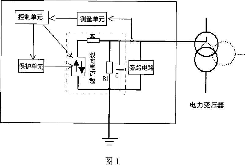
[0019] Use the method of the present invention to reduce the DC current at the neutral point of a high-voltage grid transformer. As shown in Figure 1, a controllable potential compensation device is connected in series between the neutral point of the power transformer and the grounding electrode. A controlled bidirectional current source, compensating resistor R1 and shunt resistor R2 form a series loop, in which the compensating resistor R1 is connected in series between the neutral point of the grounding transformer and the grounding electrode, and the compensating resistor R1 is connected in parallel with a bypass protection capacitor C and a manual The bypass circuit; at the same time, it is equipped with a measuring unit (transformer neutral point DC monitor), a control unit and a protection unit; the measuring unit measures the neutral point DC current of the transformer, and obtains the neutral point DC current value and direction; the measuring unit and The control uni...

Embodiment 2

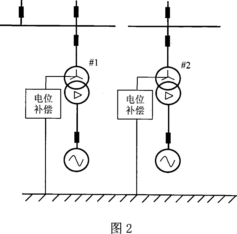
[0021] This embodiment is an example of setting independent potential compensation devices for two transformers #1 and #2 in the same substation to reduce the neutral point DC current of the two transformers, as shown in FIG. 2 . The potential compensation devices and related devices provided by the two transformers are basically the same as those in the first embodiment. Due to the network structure, the DC currents of the neutral points of #1 and #2 transformers are respectively 26.45A and 37.61A, which are somewhat different.

[0022] The experiment of suppressing the neutral point current of two transformers by using the potential compensation method of the present invention includes implementing potential compensation to only one transformer and implementing potential compensation to two transformers at the same time.

[0023] See Table 1 for the effects of suppressing the neutral point currents of the two transformers through the potential compensation method of the pres...


PUM

PropertyMeasurementUnit
Resistanceaaaaaaaaaa

Abstract

The invention provides a potential compensation method for eliminating and weakening the DC current of a transformer neutral point in high voltage power network. The method adds a controllable potential compensation device between the neutral point of grounding transformer in power station and a ground pole in series, the DC current of the transformer neutral point is measured by a transformer neutral point DC monitor, and a control unit controls the current output of a bipolar current source based on the measured DC current of the transformer neutral point, and then the potential compensation device generates a compensation potential which partly or fully compensates the potential variety of each grounding pole in AC grid generated by neutral current thereby making the potentials of each grounding transformer neutral point in the AC grid similar to or close to each other, thus the DC current of the transformer neutral point in high voltage power network can be effectively restrained. The provided method can conquer the weaknesses existing in current engineering application methods such as capacitor DC blocking method, small resistance current limiting method, neutral point injecting reverse current limiting method.

Description

technical field [0001] The invention relates to a method for suppressing the neutral-point direct current of a high-voltage network transformer in a high-voltage power transmission and transformation system. Background technique [0002] Since the EHVDC transmission system was put into operation, there have been frequent occurrences of ground currents causing DC bias and aggravated vibration of AC grid grounding transformers, affecting the safety of power equipment. To solve this problem, the DC current at the neutral point of the transformer must be effectively reduced. At present, the methods for limiting the neutral point DC current of transformers in engineering applications mainly include: capacitor DC blocking method and small resistor current limiting method. The capacitor DC blocking method can completely eliminate the neutral point DC current, but it affects the effective grounding of the transformer, increases the insulation requirements of the main transformer, a...

Claims


Application Information

Patent Timeline
IPC IPC(8): H02H9/02H02H7/04H01F27/42
Inventor 马志强
Owner 广东西格特电气设备有限公司
Learn More