

Lift installation
A technology for elevators and drives, used in elevators, transportation and packaging, elevators, etc. in buildings
- Summary
- Abstract
- Description
- Claims
- Application Information
AI Technical Summary
Problems solved by technology
Method used
Image

Examples
Embodiment approach 1
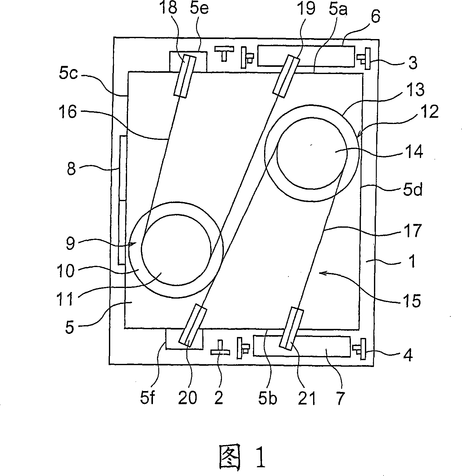
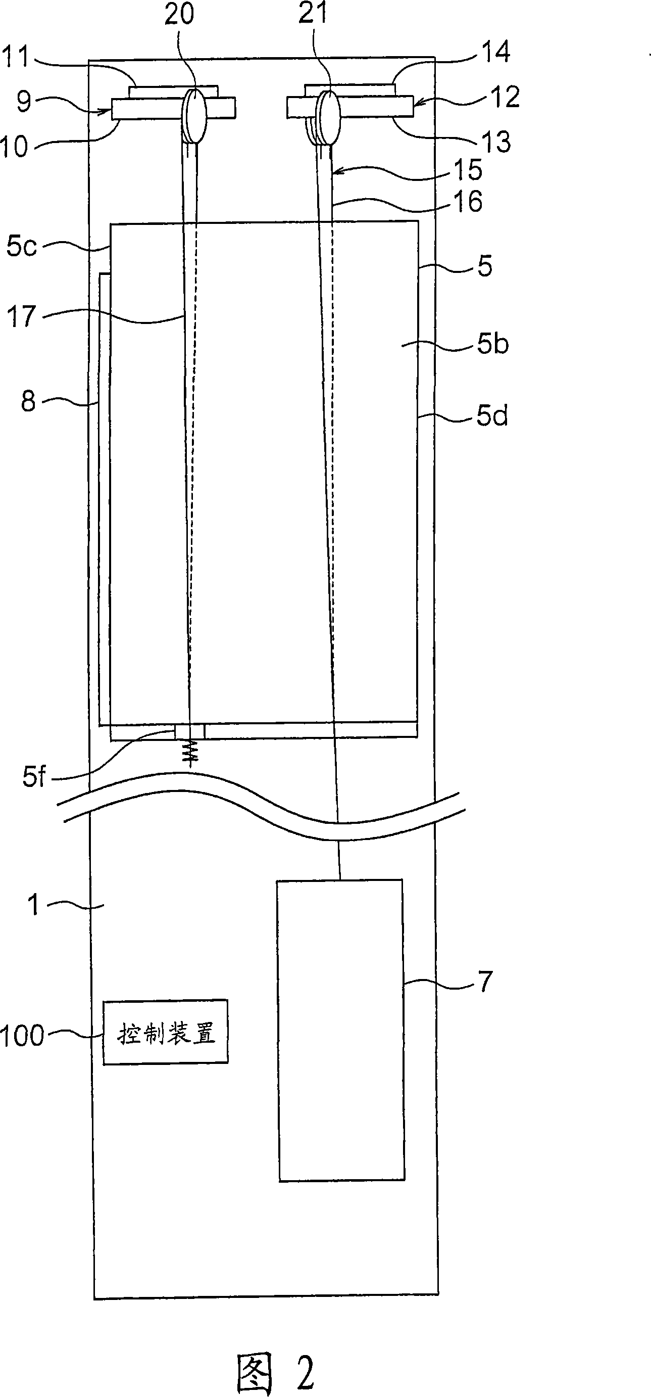
[0039] Fig. 1 is a plan view of an elevator apparatus according to Embodiment 1 of the present invention, and Fig. 2 is a side view of the elevator apparatus of Fig. 1 . In the above figure, a pair of car guide rails 2 , a pair of first counterweight guide rails 3 , and a pair of second counterweight guide rails 4 are provided in the hoistway 1 .
[0040] The arrangement of the car guide rails 2 is such that, in the vertical projection plane, the straight line connecting the two car guide rails 2 extends parallel to the opening direction of the landing entrance. The configuration of the first counterweight guide rails 3 is that, in the vertical projection plane, the straight line connecting the two first counterweight guide rails 3 extends along the depth direction of the hoistway 1 . The configuration of the second counterweight guide rails 4 is that, in the vertical projection plane, the straight line connecting the two second counterweight guide rails 4 extends along the de...
Embodiment approach 2
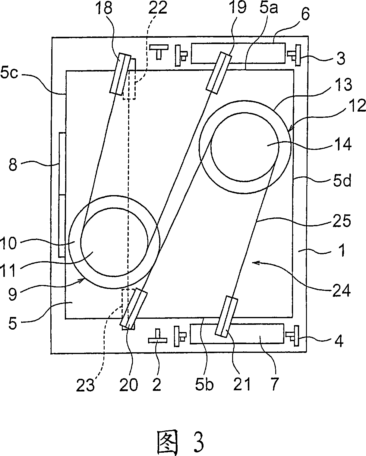
[0065] Next, FIG. 3 is a plan view of an elevator apparatus according to Embodiment 2 of the present invention, and FIG. 4 is a side view of the elevator apparatus of FIG. 3 . In the above-mentioned figures, the first and second car suspension pulleys 22, 23 are arranged at the bottom of the car 5, and the first car suspension pulley 22 and the second car suspension pulley 23 are located at the bottom of the car 5. There are intervals in the width direction. The first and second car suspension pulleys 22, 23 are arranged such that their rotation axes are in a horizontal state and extend parallel to the depth direction of the hoistway 1. As shown in FIG.
[0066] The car 5 and the first and second counterweights 6 , 7 are suspended in the hoistway 1 by the main rope body 24 . The main rope body 24 has a plurality of (only one is shown in the figure) main ropes 25 . The main rope 25 has a first end connected to the first counterweight 6 and a second end connected to the second...
Embodiment approach 3
[0072] Next, Fig. 5 is a top view of an elevator device according to Embodiment 3 of the present invention. In this embodiment, the second counterweight 7 is disposed on the front side of the car guide rail 2 in the depth direction of the hoistway 1 . The first and second rope connecting portions 5e, 5f are arranged in such a way that a straight line connecting the first rope connecting portion 5e and the second rope connecting portion 5f passes through the center of gravity C of the car 5 in the vertical projection plane. That is, the car 5 is substantially suspended by the main rope body 15 at the position of the center of gravity.
[0073] With such an elevator device, the driving devices 9, 12 and the counterweights 6, 7, etc. can be more effectively arranged, making the overall arrangement space more compact. That is, the arrangement position of the first counterweight 6 and the arrangement position of the second counterweight 7 may be shifted from each other in the dept...
PUM
 Abstract
Description
Claims
Application Information