Aplanatic light path control device of laser cutter

A laser cutting machine and control device technology, applied in laser welding equipment, manufacturing tools, welding equipment, etc., can solve the problems of complex structure, high cost, low precision, etc., and achieve stable movement, improved cutting quality, and compact installation space Effect

Inactive Publication Date: 2009-09-23
WUHAN FARLEY LASERLAB CUTTING WELDING SYST ENG CO LTD
View PDF1 Cites 3 Cited by
  • Summary
  • Abstract
  • Description
  • Claims
  • Application Information

AI Technical Summary

Problems solved by technology

[0003] At present, in the field of large-format laser processing, in order to ensure that the diameter of the spot within the processing range remains unchanged, the method of adding a compensation mirror seat to the transmission optical path is often used. Chinese patent 200620144696.6 provides a compensation device. The device Adding an independent drive mechanism and a pair of moving guide rails, not only has a complex structure, high cost and low precision

Method used


Image

  • Aplanatic light path control device of laser cutter
  • Aplanatic light path control device of laser cutter

Examples


Embodiment Construction

[0013] Further illustrate the concrete structure of the present invention below in conjunction with accompanying drawing:

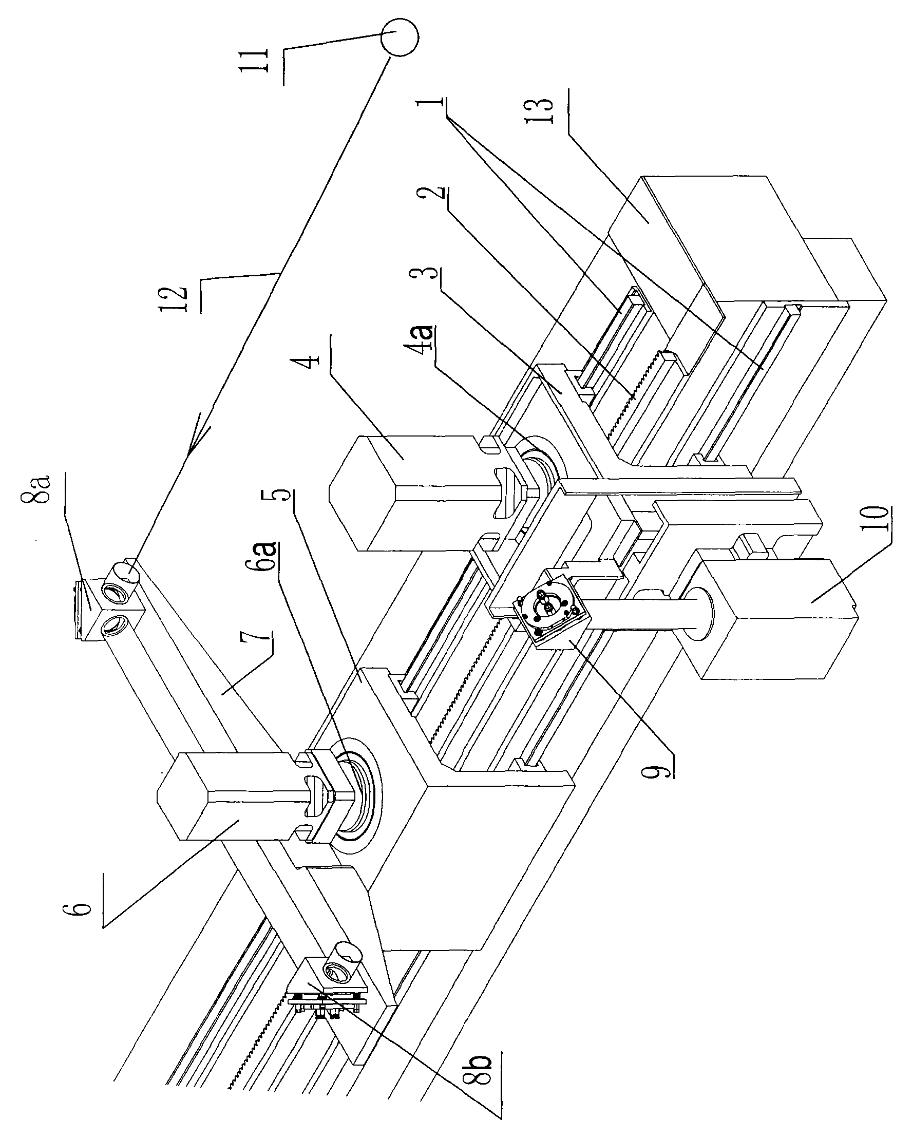
[0014] figure 1 It is a schematic diagram of the overall structure of the present invention in the application state:

[0015] The present invention mainly comprises the laser source 11, the compensating reflector mechanism on the optical path 12 and its compensating mechanism drive, the laser cutting head reflector 9 on the laser cutting head 10, the driving 4 of the laser cutting head, the compensating reflector mechanism and the laser cutting head Share a linear guide rail pair 1 on the crossbeam 13, and the compensation drive and the laser cutting head drive the same transmission pair 2 on the shared crossbeam.

[0016] The linear guide rail pair 1 and the rack 2 are fixed on the beam 13, and the sliding seat 3 is installed on the linear guide rail pair 1, matches with the linear guide rail pair 1, and can slide on the linear guide rail pair 1. Slid...


PUM


Abstract

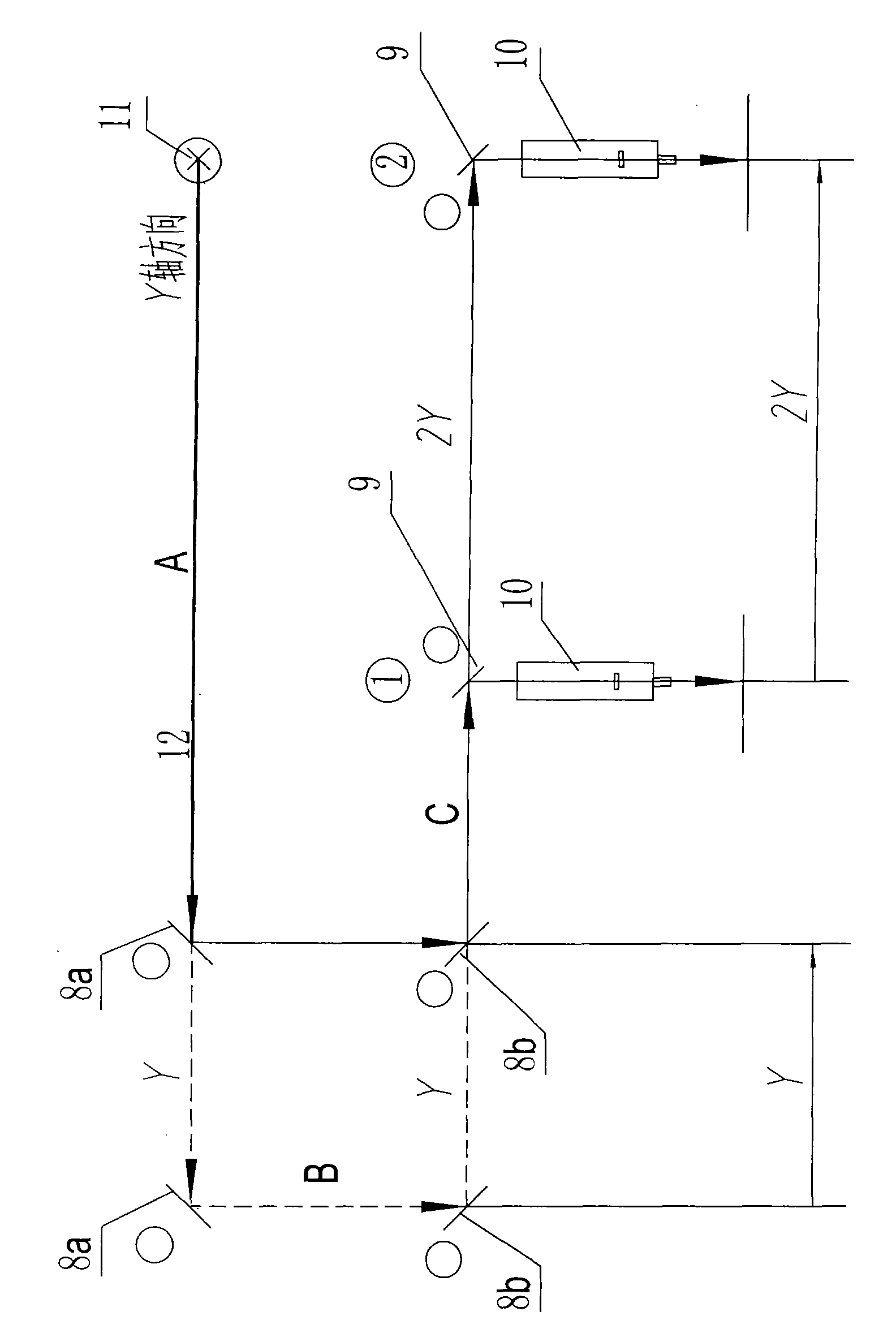
The invention provides an aplanatic light path control device of a laser cutter. The device comprises a laser source, a compensation reflector mechanism on the light path and a compensation mechanism driver thereof, a reflector on a laser cutting head, and the laser cutting head and a driver thereof. The compensation reflector mechanism and the laser cutting head share a linear guide rail pair on a cross beam, and the compensation mechanism driver and the laser cutting head driver share a transmission pair on the cross beam; and the motion direction of the compensation reflector mechanism is corresponding to that of the laser cutting head and the motion begins and stops at the same time, and the ratio of the motion velocity V1 of the compensation reflector mechanism on the cross beam linear guide rail pair and the motion velocity V2 of the laser cutting head on the cross beam linear guide rail pair is as follows: V1:V2=1:2. The motion distance of the compensation reflector mechanism is Y when the motion distance of the laser cutting head along the Y axis is 2Y, thus ensuring constant light path length.

Description

technical field [0001] The invention relates to an optical path control device for a laser cutting machine. The device is a matching device for the laser cutting machine, and is used to keep the transmitted optical path length constant during the laser cutting process, so as to ensure the same cutting effect within the effective processing range. quality. Background technique [0002] During the laser cutting process, due to the influence of the beam divergence angle of the laser itself, the change of the optical path length will lead to the change of the diameter of the beam before focusing. The larger the diameter of the incident beam, the smaller the diameter of the focal spot. In order to reduce the change of the focus spot size caused by the change of the beam size before focusing, the method of adding an equal optical path device is adopted to compensate the optical path, that is, when the optical path increases due to remote processing, the compensation optical path i...

Claims


Application Information

Patent Timeline
Patent Type & Authority Applications(China)
IPC IPC(8): B23K26/06B23K26/08B23K26/38B23K26/064
Inventor 邓家科李斌李家军王晟
Owner WUHAN FARLEY LASERLAB CUTTING WELDING SYST ENG CO LTD
Why Eureka
Try Eureka