Sensor and method for manufacturing a sensor

a sensor and sensor technology, applied in the field of sensors, can solve problems such as affecting the behavior of inertia weight, and achieve the effects of reducing manufacturing costs, reducing manufacturing costs, and reducing manufacturing tolerances when positioning the cap

Inactive Publication Date: 2011-09-22
ROBERT BOSCH GMBH
View PDF10 Cites 2 Cited by
  • Summary
  • Abstract
  • Description
  • Claims
  • Application Information

AI Technical Summary

Benefits of technology

[0005]In contrast to the related art, the sensor according to the present invention and the method according to the present invention for manufacturing a sensor according to the other independent claims have the advantage that on the one hand, the deflection of the seismic mass is limited by the first and second stops and on the other hand, the behavior of the seismic mass is not influenced or is only immaterially influenced by the first and second stops. Furthermore, the sensor according to the present invention may be manufactured comparatively simply and cost-effectively, since the design of the first and second stops as part of the cap for positioning the first and second stops only makes it necessary to place the cap on the substrate. Furthermore, the manufacturing tolerances when positioning the cap on the substrate parallel to the main extension plane in particular are substantially increased in the sensor according to the present invention. This is achieved in that the first and second coverage regions are essentially of equal size, so that in particular in the case of an electrically conductive contact between the first and second stops across the rest of the cap, a first electrostatic interaction between the first area and the first stop is equal to a second electrostatic interaction between the second area and a second stop. Thus, the first and second electrostatic interactions on the seismic mass are offset and no or only an insignificant resulting torque acts on the seismic mass having an axis of rotation parallel to the main extension plane. The first and second stops are placed on the substrate using the cap in particular in such a way that when the cap is displaced in relation to the substrate parallel to the main extension plane, the size of the first coverage region changes to be equal to the size of the second transition area and accordingly the cap need not be positioned as precisely on the substrate, but nonetheless compensation is achieved between the first and second electrostatic interactions. In particular a measurement of an acceleration perpendicular to the main extension plane, i.e., in the z direction, is not or is only insignificantly influenced by the first and second stops. Furthermore, for example, a measurement of an acceleration parallel to the main extension plane, i.e., in the x and / or y direction, is also not influenced or is only insignificantly influenced by the first and second stops, since the first and second electrostatic interactions have at most a uniform force effect on the seismic mass in the z direction, and accordingly a tipping of the seismic mass about the axis of rotation parallel to the main extension plane is prevented, such a tipping entailing the risk of displacement of the center of mass of the seismic mass in the x and / or y direction and accordingly a falsification of the measurement.

Problems solved by technology

A disadvantage of this system for shortening the possible deflection of the inertia weight in the z direction is that a one-sided electrostatic interaction between the inertia weight and the stop device influences the behavior of the inertia weight.

Method used


Image

  • Sensor and method for manufacturing a sensor
  • Sensor and method for manufacturing a sensor
  • Sensor and method for manufacturing a sensor

Examples


Embodiment Construction

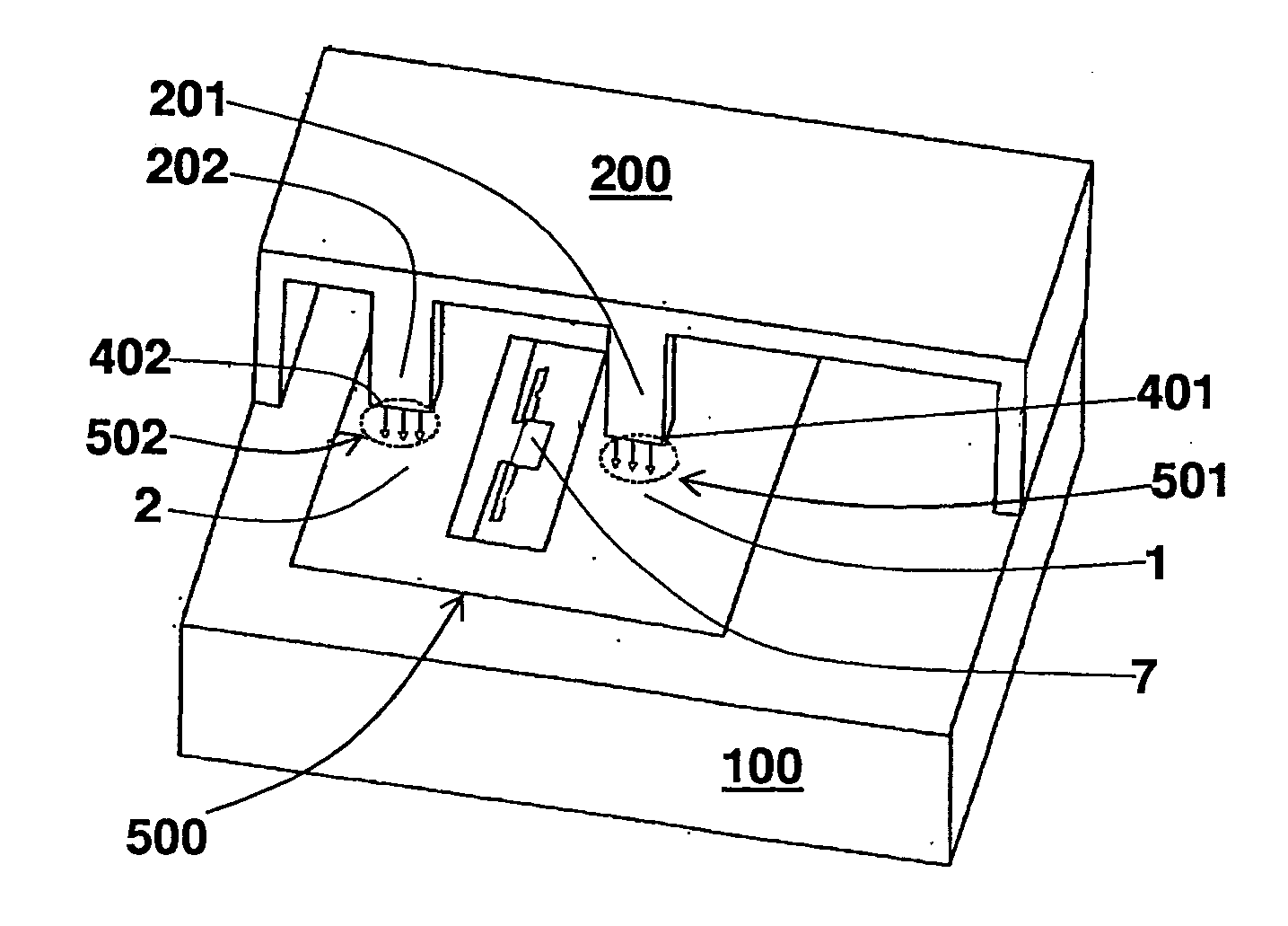
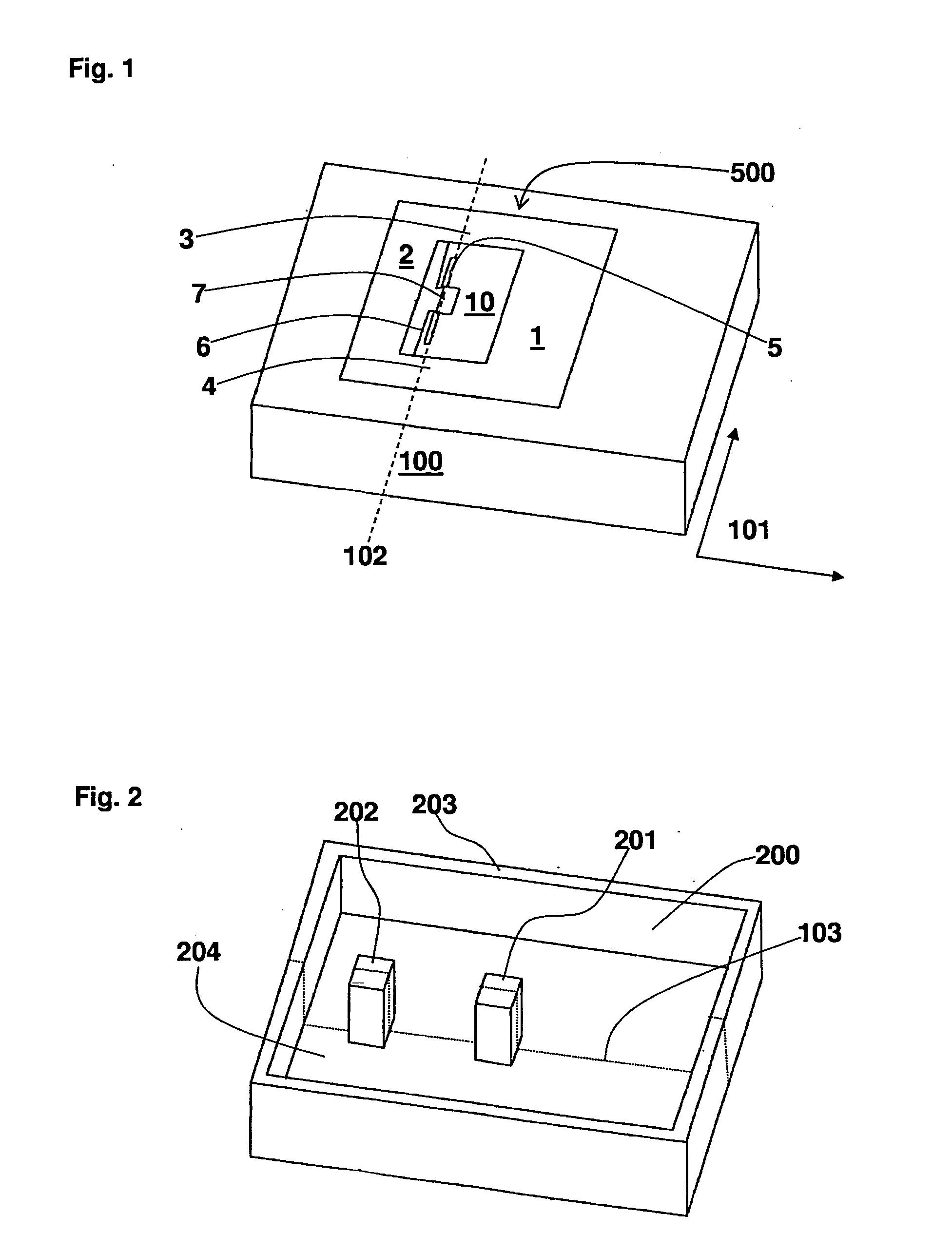
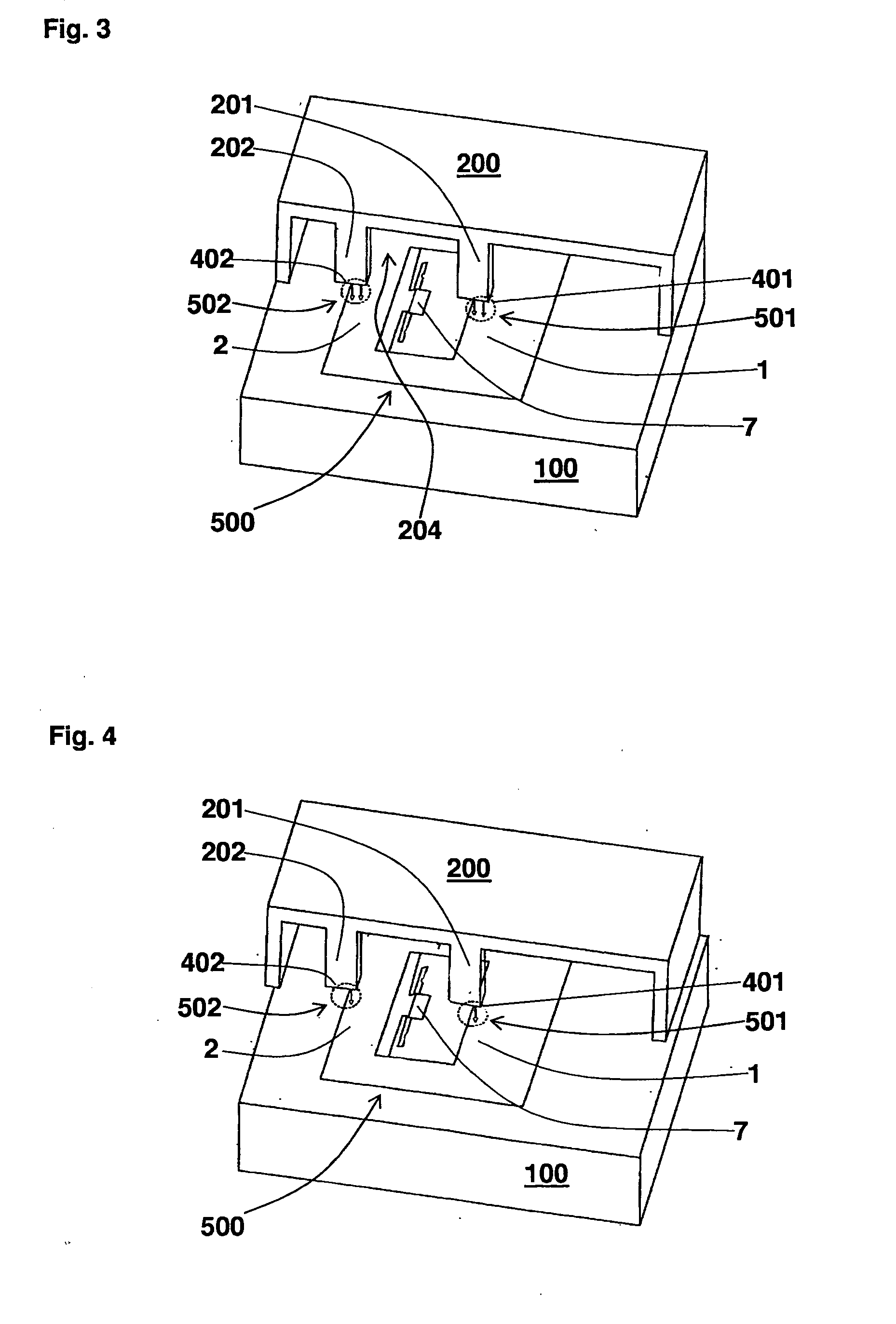
[0020]A schematic perspective view of a substrate 100 and a seismic mass 500 of a sensor according to a first specific embodiment of the present invention is represented in FIG. 1, substrate 100 having a main extension plane 101 and completely enclosing seismic mass 500 in a plane parallel to main extension plane 101. Seismic mass 500 includes a first seismic partial mass 1 and a second seismic partial mass 2, first and second seismic partial masses 1, 2 being joined to one another by a first and a second web 3, 4. An open space 10 is provided between first and second seismic partial masses 1, 2 and between first and second webs 3, 4. Alternatively, open space 10 includes an area which is connected to the electrical potential of substrate 100. Situated in open space 10 is an anchoring element 7 which is connected to substrate 100. Seismic mass 500 is attached to anchoring element 7 using suspension springs 5, making a movement of seismic mass 500 relative to substrate 100 possible. ...


PUM

PropertyMeasurementUnit
sizeaaaaaaaaaa
seismic massaaaaaaaaaa
areaaaaaaaaaaa

Abstract

A sensor having a substrate, a cap and a seismic mass is proposed, the substrate having a main extension plane, the seismic mass being deflectable perpendicular to the main extension plane, a first stop of the cap covering a first area of the seismic mass perpendicular to the main extension plane in a first coverage region and a second stop of the cap covering a second area of the seismic mass perpendicular to the main extension plane in a second coverage region, and furthermore the first and second coverage regions parallel to the main extension plane being essentially equal in size. The distances of the coverage regions from a pivot axis of the mass designed as a rocker are equal so that the torques caused by electronic forces offset one another.

Description

BACKGROUND OF THE INVENTION[0001]1. Field of the Invention[0002]The present information is generally directed to a sensor.[0003]2. Description of Related Art[0004]Such sensors are generally known. For example, a micromechanical acceleration sensor having an inertia weight in the form of a rocker which is deflectable in the z direction is known from publication published German patent document DE 10 2006 026 880 A1, a stop device being provided on the side of the shorter lever arm for shortening the possible deflection if the lever arms of the rocker are of varying lengths in order to prevent asymmetrical clipping. A disadvantage of this system for shortening the possible deflection of the inertia weight in the z direction is that a one-sided electrostatic interaction between the inertia weight and the stop device influences the behavior of the inertia weight. Furthermore, publication published German patent document DE 198 00 574 A1 describes an acceleration sensor having a capping ...

Claims


Application Information

Patent Timeline
Patent Type & Authority Applications(United States)
IPC IPC(8): G01P15/02H05K3/00
CPCG01P15/0802B81B3/0051Y10T29/49124B81B2203/058B81C2203/0109B81B2201/0235G01P2015/0831
Inventor WELLNER, PATRICKPATAK, CHRISTIANTEBJE, LARSGRUTZECK, HELMUTMATERNA, VOLKER
Owner ROBERT BOSCH GMBH
Why Eureka
Try Eureka