
Triangular wave phase modulation method of resonant cavity optical fiber gyroscope and apparatus thereof

A phase modulation, fiber optic gyroscope technology, applied in measurement devices, coupling of optical waveguides, Sagnac effect gyroscopes, etc., can solve problems such as affecting system accuracy, inaccurate 2π reset height, and unfavorable signal carrier component suppression. , to achieve the effect of overcoming the influence and suppressing the noise

Inactive Publication Date: 2007-09-26
ZHEJIANG UNIV
View PDF0 Cites 32 Cited by
  • Summary
  • Abstract
  • Description
  • Claims
  • Application Information

AI Technical Summary

Benefits of technology

This technology helps prevent interference from scattered light waves that can cause errors during signal processing or affect other components' performance. It also prevents changes made due to external influences like temperatures which could change how much it causes an error when analyzed with another type of sensor.

Problems solved by technology

This patented technical problem addressed in this patents relates to improving the performance of an electronic or optoelectrooptic instrument called a resonant cavity fibers optics gyro due to its low sensitivity to external factors like temperature changes and vibrations during operation. Current methods for reducing unwanted signals such as light scatter from nearby objects can be affected negatively, making them difficult to accurately determine their position with respect to time. To address these issues, research has been done on various ways to reduce interference between different types of electromagnetic waves transmitted through the oscillating mirror.

Method used


Image

  • Triangular wave phase modulation method of resonant cavity optical fiber gyroscope and apparatus thereof
  • Triangular wave phase modulation method of resonant cavity optical fiber gyroscope and apparatus thereof
  • Triangular wave phase modulation method of resonant cavity optical fiber gyroscope and apparatus thereof

Examples


Embodiment Construction

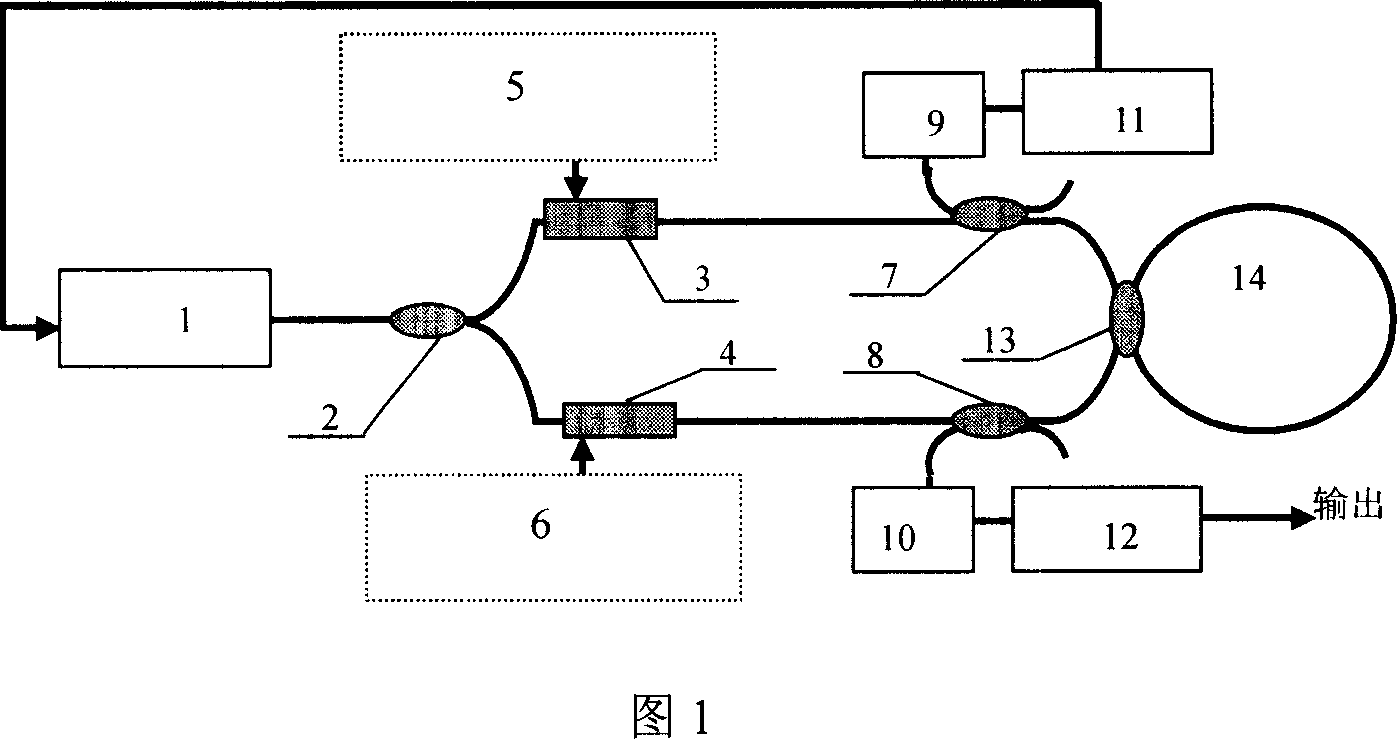
[0024] As shown in Figure 1, in the triangular wave phase modulation device of the resonator fiber optic gyroscope, the laser 1 and the first coupler 2, the first phase modulator 3, the second coupler 7, the third coupler 13, and the fourth coupler 8 , the second phase modulator 4, the first coupler 2 are connected, the first phase modulator 3 is connected with the first triangular wave signal generator 5, the second phase modulator 4 is connected with the second triangular wave signal generator 6, The second coupler 7 is connected with the first photodetector 9, the first high-speed digital signal processor 11, and the laser 1, and the fourth coupler 8 is connected with the second photodetector 10 and the second high-speed digital signal processor 12. , the third coupler 13 is connected to the fiber ring 14 .

[0025] The laser light emitted by the laser (Laser) is divided into two beams by the 50% coupler C1, and the two beams are frequency-shifted by the phase modulator (Ph...


PUM


Abstract

This invention discloses one triangle wave phase modulation method and device of resonance chamber fiber top, wherein, the laser is connected to first couple device, first phase modulator, second couple device, third couple device, fourth couple device, second phase modulation device and first couple; the first phase modulation and first triangle wave signal generator are connected; the second phase modulation and second triangle signal generator are connected; the second couple device and first photoelectricity, first high speed digital signal processor and laser are connected; the fourth couple device is connected to fourth couple device, second photoelectricity detector, second high speed digital processor; the third couple device is connected to the fiber ring.

Description


Claims


Application Information

Patent Timeline
Owner ZHEJIANG UNIV
Learn More