
Back light module unit and light conducting plate thereof

A technology of backlight module and light guide plate, applied in the direction of light guide, optics, optical components, etc., can solve the problem of difficulty in eliminating fireflies, and achieve the effect of eliminating firefly phenomenon and reducing energy

Inactive Publication Date: 2007-09-26
HONG FU JIN PRECISION IND (SHENZHEN) CO LTD +1
View PDF0 Cites 9 Cited by
  • Summary
  • Abstract
  • Description
  • Claims
  • Application Information

AI Technical Summary

Problems solved by technology

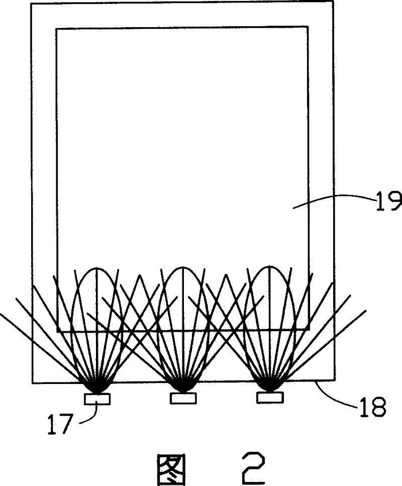
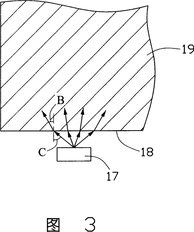
The incident light passes through the above structure, resulting in refraction and beam expansion, which can eliminate the light column at the light source to a certain extent, but it is usually difficult to eliminate the phenomenon of fireflies in one split

Method used


Image

  • Back light module unit and light conducting plate thereof
  • Back light module unit and light conducting plate thereof
  • Back light module unit and light conducting plate thereof

Examples


Embodiment Construction

[0024] The backlight module and its light guide plate of the present invention will be further described in detail below with reference to the drawings and embodiments.

[0025] Please refer to FIG. 6 and FIG. 7 at the same time. The first embodiment of the present invention provides a backlight module 30 . The backlight module 30 includes a light guide plate 31 and a light source 33 located on one side of the light guide plate 31. The light source 33 is composed of a plurality of LED light sources. The light splitting groove 32 is a cylindrical hole with an arcuate cross section, and the light splitting groove 32 can be a through hole or a blind hole. When the light L emitted from the light source 33 passes through the incident surface 311, due to the refractive index n of the air 0 greater than the refractive index n of the light guide plate 31 1 , the first refraction will occur. The incident angle of light entering the light splitting groove 32 becomes B, and since the ...


PUM


Abstract

This invention provides one aphototropism module set, which comprises one light conductive board, light source in at least one side of board, wherein, the board comprises at least one incidence surface and one exit one; the board is set with one light split structure set inside the board near to the split tank of the incidence surface.

Description

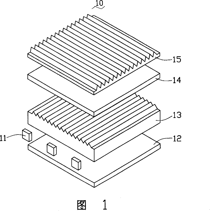
【Technical field】 [0001] The invention relates to a backlight module and its light guide plate, in particular to a backlight module and its light guide plate for liquid crystal display devices. 【Background technique】 [0002] Since the liquid crystal itself of the liquid crystal display panel does not have light-emitting characteristics, in order to achieve a good display effect, it is necessary to provide a side light source device for the liquid crystal display panel, such as a backlight module, whose function is to supply sufficient luminance to the liquid crystal display panel and Evenly distributed surface light source. [0003] Please refer to FIG. 1 , the current traditional backlight module 10 generally includes optical films such as a light source 11 , a light guide plate 13 , a reflector 12 , a diffusion sheet 14 , and a prism sheet 15 . The light guide plate 13 is used to guide the scattering direction of the light, so that the light is uniformly emitted from the...

Claims


Application Information

Patent Timeline
IPC IPC(8): G02F1/13357G02B6/00G02F1/1335
Inventor 朱文武吴叶
Owner HONG FU JIN PRECISION IND (SHENZHEN) CO LTD
Learn More