Method of producing magnetic head and magnetic head

A manufacturing method and magnetic head technology, applied to magnetic recording heads, orthogonal magnetized magnetic heads, magnetic heads using thin films, etc., can solve the problems of difficulty and trouble in the magnetic layer 26, and achieve the effects of preventing thickness changes and high reliability

Inactive Publication Date: 2007-09-26
FUJITSU LTD
View PDF1 Cites 0 Cited by
  • Summary
  • Abstract
  • Description
  • Claims
  • Application Information

AI Technical Summary

Problems solved by technology

Therefore, it is difficult and troublesome to perform a polishing step to form the magnetic layer 26 with a prescribed thickness and core width.

Method used


Image

  • Method of producing magnetic head and magnetic head
  • Method of producing magnetic head and magnetic head
  • Method of producing magnetic head and magnetic head

Examples


no. 1 example

[0032] Referring to FIGS. 1A-1E and 2A-2F, the first embodiment of the magnetic head fabrication method will be described. Note that the magnetic head of the present invention is a perpendicular magnetic head.

[0033] Like the typical vertical magnetic head shown in FIG. 4, the vertical magnetic head of the present embodiment includes a read head 8 and a write head 10, and the lower shield layer 5, the MR element 6 and the upper shield layer 7 of the read head 8 are plated or sputtering formed on the substrate. The main magnetic pole 12, the return yoke 14, the coil, and the like of the write head 10 are formed in a predetermined pattern by plating or sputtering.

[0034] Next, the forming process of the main magnetic pole 12, which is a unique feature of the present invention, will be described.

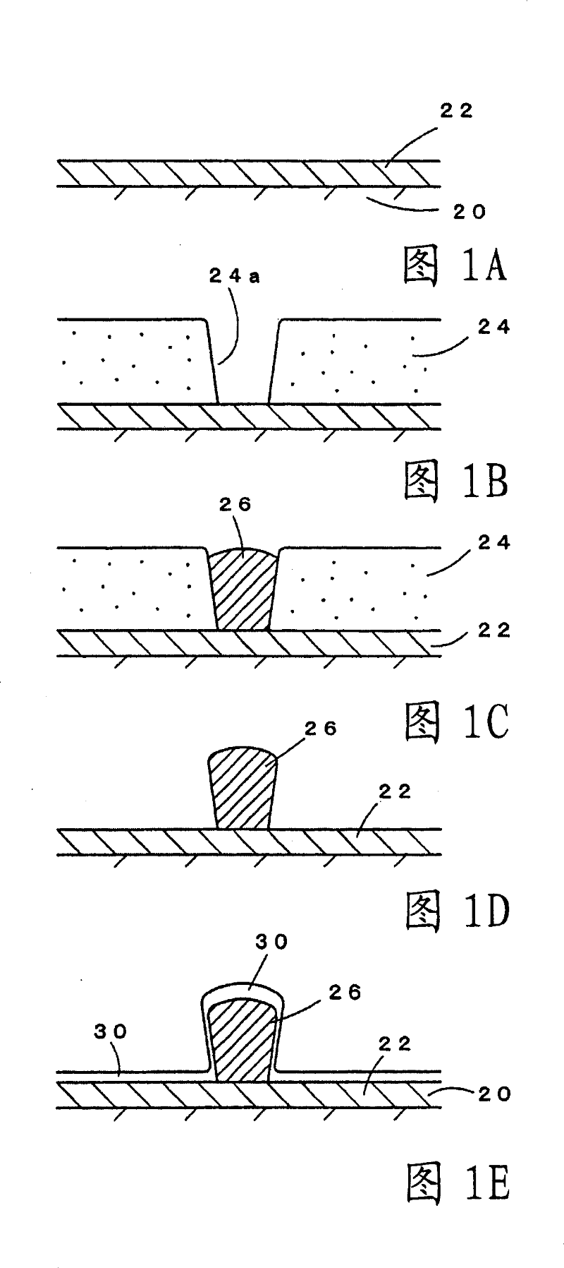
[0035] 1A-1E show the steps up to the formation of the magnetic layer 26, which becomes the main magnetic pole.

[0036] In FIG. 1A, a seed layer 22 made of, for example, ruthen...

no. 2 example

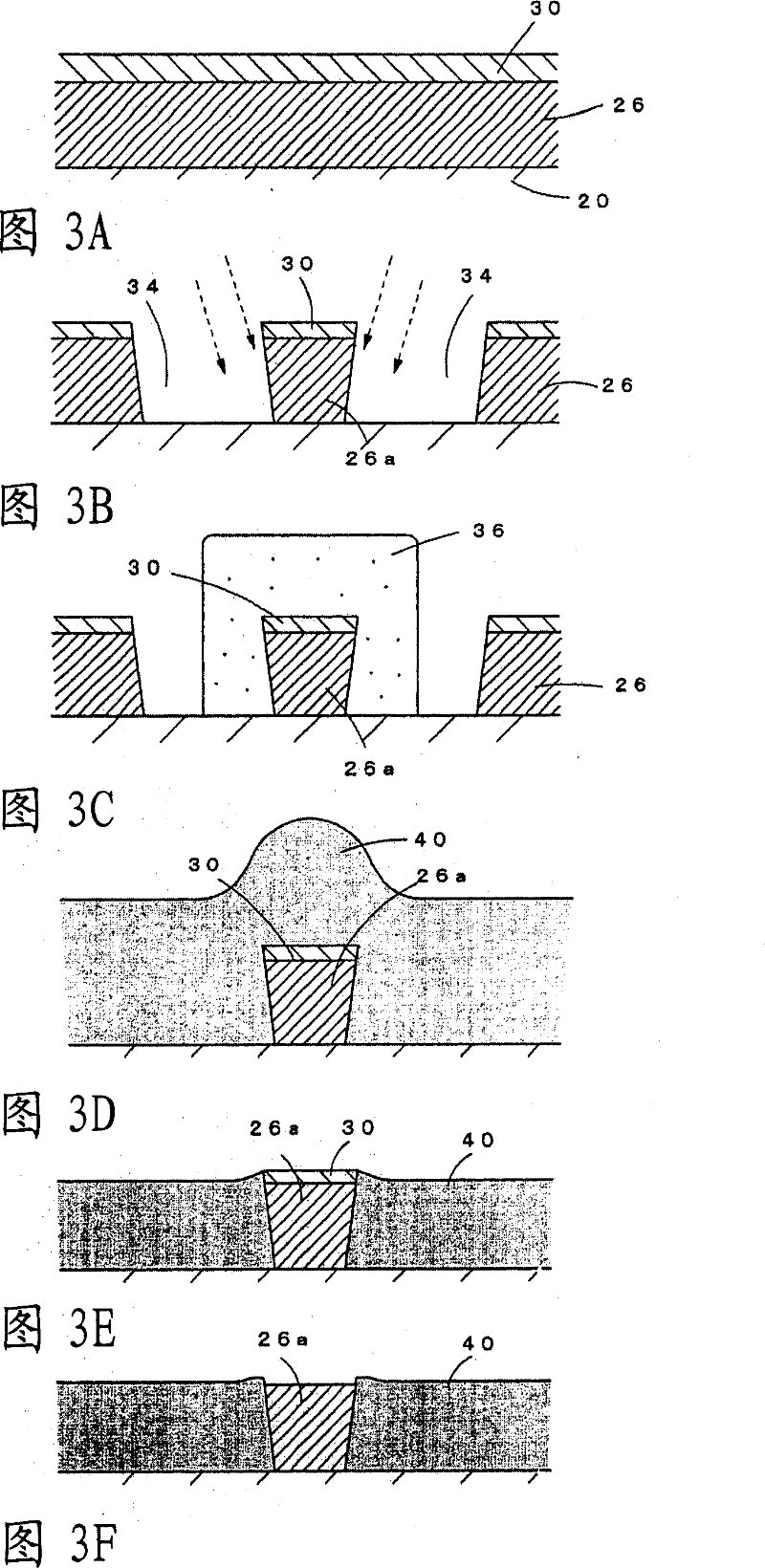
[0058] Next, with reference to FIGS. 3A-3F , the second embodiment of the magnetic head manufacturing method will be described. Note that, like the first embodiment, the magnetic head of the present invention is a perpendicular magnetic head. In this embodiment, the magnetic layer 26 is formed by a dry process such as sputtering, and the magnetic poles are formed by a FIB process. The same reference numerals are assigned to the structural elements explained in the first embodiment.

[0059] In FIG. 3A , the magnetic layer 26 is formed on the base layer 20 by sputtering, and the blocking layer 30 is formed on the surface of the magnetic layer 26 . The thickness of the magnetic layer 26 corresponds to the thickness of the main magnetic pole 26a in advance. Like the first embodiment, the stopper layer 30 is made of a material having a low polishing rate such as tantalum. The blocking layer 30 acts as a blocking layer when the magnetic layer 26 is etched by the FIB. Therefore,...


PUM

PropertyMeasurementUnit
thicknessaaaaaaaaaa

Abstract

The method of the present invention is capable of highly precisely producing a magnetic head. The method comprises the steps of: forming a pole end part of a magnetic layer, which becomes a magnetic pole and which is formed on a surface of a work piece on which the magnetic head will be formed, into a prescribed shape; coating at least a top part of the magnetic layer with a stopper layer; coating a surface of the work piece, on which the stopper layer has been formed, with an insulating layer, whose polishing rate is higher than that of the stopper layer; polishing the surface of the work piece until the stopper layer, which coats the top part of the magnetic layer, is exposed from the insulating layer; and removing the stopper layer, which has been exposed in a surface of the magnetic layer.

Description

technical field [0001] The present invention relates to a method of manufacturing a magnetic head and a magnetic head, and more precisely, to a method of manufacturing a magnetic head preferably applied to forming a high-precision magnetic head such as a main pole of a perpendicular magnetic head, and a magnetic head manufactured by the method. Background technique [0002] A typical perpendicular head of a disk drive unit is shown in FIG. 4 . The perpendicular magnetic head includes: a read head 8, in which an MR element 6 is sandwiched between a lower shield layer 5 and an upper shield layer 7; a write head 10, in which a A writing gap 13; and a recording coil 15 are formed. [0003] A perpendicular magnetic head with a main pole 12 suffers from side track erasure, which is caused by the shape of the pole tip of the main pole 12 . [0004] Side rail erasure is explained below. The angle of inclination is different when the arm holding the head is inside the recording me...

Claims


Application Information

Patent Timeline
Patent Type & Authority Applications(China)
IPC IPC(8): G11B5/127G11B5/31
CPCG11B5/3169G11B5/1871G11B5/1278Y10T29/49037G11B5/3116G11B5/3163
Inventor 橘雅典竹下弘人
Owner FUJITSU LTD
Why Eureka
Try Eureka