Voltage switching device

A voltage switching and voltage technology, applied in output power conversion devices, electrical components, adjusting electrical variables, etc., can solve the problems of increasing the circuit layout area and consuming the overall system power, and achieve the effect of saving circuit layout area and reducing power.

Inactive Publication Date: 2007-09-26
HIMAX TECH LTD
View PDF0 Cites 2 Cited by
  • Summary
  • Abstract
  • Description
  • Claims
  • Application Information

AI Technical Summary

Problems solved by technology

In this way, it not only increases the layout area of ​

Method used


Image

  • Voltage switching device
  • Voltage switching device
  • Voltage switching device

Examples


Example Embodiment

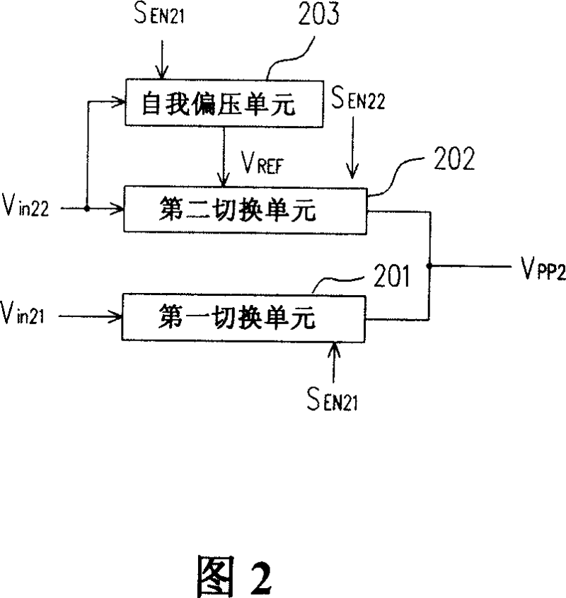
[0027] FIG. 2 is a structural diagram of a voltage switching device according to an embodiment of the present invention. As shown in FIG. 2 , the voltage switching device includes a first switching unit 201 , a second switching unit 202 , and a self-biasing unit 203 . The first switching unit 201 and the second switching unit 202 respectively receive the input voltage V in21 with V in22 , and the output end of the first switching unit 201 is electrically connected to the output end of the second switching unit 202 . The self-bias unit 203 is connected to the second switching unit 202 for providing a reference voltage V REF to the second switching unit 202. In this voltage switching device, according to the enabling signal S EN21 Controlling the first switching unit 201 and the self-biasing unit 203, according to the enabling signal S EN22 and the reference voltage V REF Control the second switching unit 202 so that the voltage switching device generates a switching volta...


PUM


Abstract

A voltage switching device is used to receive several input voltage and output switch voltage; it includes the first switching unit, the second switching unit and the self bias voltage unit. The voltage switching device generates the switching voltage according to the output of the first switch unit and the second switching unit. The reference voltage output by the self bias voltage unit is sent to the second switch unit. The first switching unit outputs the first input voltage as the switching voltage according to the first energy signal. The second switch unit outputs the second input voltage as the switching voltage according to the second energy signal.

Description

technical field [0001] The present invention relates to a voltage switching device, and in particular to a voltage switching device using a self-bias circuit. Background technique [0002] With the emergence of a large number of portable products, efficient power management has become one of the important factors in circuit design. In the field of power efficiency design, one of them is that a variety of different switching voltages must be provided for system components to achieve low power and highly integrated electronic products. [0003] FIG. 1 is a conventional voltage switching device, which includes switches S11 and S12. The first ends of the switches S11 and S12 respectively receive the input voltage V in11 with V in12 , and the second ends of the switches S11 and S12 are electrically connected to each other and output a switching voltage V PP1 . Two non-overlap enabling signals S EN11 with S EN12 Can be used to control this voltage switching device. Switch ...

Claims


Application Information

Patent Timeline
IPC IPC(8): H02M3/00
Inventor 陈天豪
Owner HIMAX TECH LTD
Why Eureka
Try Eureka