Method and device for igniting and monitoring a burner

A burner and fuel technology, applied in the direction of burner ignition device, combustion method, gas fuel burner, etc., can solve the problems of flame symmetry interference and so on

Inactive Publication Date: 2007-09-26
SANDVIK INTELLECTUAL PROPERTY AB
View PDF0 Cites 4 Cited by
  • Summary
  • Abstract
  • Description
  • Claims
  • Application Information

AI Technical Summary

Problems solved by technology

[0009] The off-centre arrangement of the electrodes will cause a disturbance of the symmetry of the flame

Method used


Image

  • Method and device for igniting and monitoring a burner

Examples


Embodiment Construction

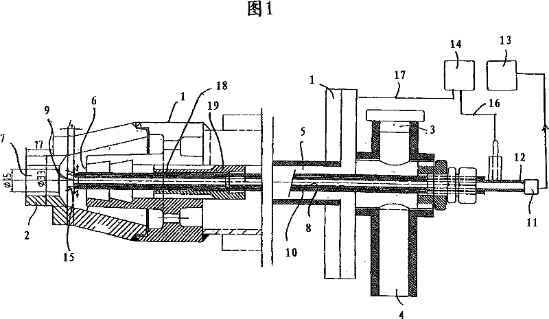
[0016] Figure 1 shows a high velocity burner designed to discharge a fuel / oxygen mixture from a burner head 2 at high velocity, where the length of the flame depends on said velocity. Figure 1 shows only the front and rear of the burner. The rear of the burner includes respective fuel and oxygen-containing gas inlets 3,4. This mixture is conveyed in a tubular channel 5 whose mouth 6 is surrounded by the burner head 2 . The burner head comprises a mixture outlet 7 and the mixture is burned outside the burner head.

[0017] According to the invention, the burner comprises a conductive tube 8 located inside and coaxially with the fuel mixture delivery channel 5 of the burner 1 . The first end 9 of the tube 8 terminates at the outlet of the fuel mixture close to the burner head.

[0018] Furthermore, the tube has an electrical insulator 10 which, according to a preferred embodiment of the invention, consists of a ceramic tube embedded in the conductive tube.

[0019] According...


PUM


Abstract

A method of igniting and monitoring a high speed burner (1) with which a fuel / oxygen- mixture exits at high velocity from a burner head (2), wherein the length of the flame is governed by the exit velocity of said mixture. The invention is characterized by placing an electrically conductive pipe (8) in and concentrical with the burner channel (5) for said fuel mixture, by causing a first end (9) of the pipe (8) to terminate close to the fuel mixture outlet (7) of the burner head (2), by electrically isolating (10) the pipe (8) and by causing the detection of light of the group ultraviolet light, visible light and / or infrared light to be detected at the other end (12) of said pipe, and by causing a spark (15) to be generated between the first end (9) of the pipe (8) and the surrounding burner head (2) by application of a voltage, in igniting the burner. The invention also relates to a burner.

Description

technical field [0001] The invention relates to a method and a device for igniting and monitoring a burner. [0002] The invention mainly concerns burners of the so-called SER type, i.e. burners with a tube in the extension of the burner head, which is surrounded by an outer tube with a closed bottom, however the invention can also relate to " Straight through" burners or open burners. Background technique [0003] Burners are generally monitored by means of electrodes located at the periphery of the flame. The electrode is coupled to an electrical circuit which cannot conduct current until the circuit is connected between the electrode and the burner or flame tube due to ionization around the flame. Alternatively, a UV detector is used for detecting UV radiation generated in the combustion state. [0004] Ionization detection requires electrodes placed at the edge of the flame, so UV detection requires the ability to capture said UV rays. [0005] In the case of so-call...

Claims


Application Information

Patent Timeline
Patent Type & Authority Applications(China)
IPC IPC(8): F23N5/08F23D14/02F23Q3/00F23N
CPCF23Q3/008F23D14/02F23N5/082F23D2207/00F23N5/08F23Q3/00
Inventor B·约恩松K·科尔霍宁P·梅恩帕T·莱温
Owner SANDVIK INTELLECTUAL PROPERTY AB
Why Eureka
Try Eureka