Gas cell using two parabolic concave mirrors and method of producing gas sensor using the same

A parabolic and concave mirror technology, applied in instruments, scientific instruments, material analysis by optical means, etc., can solve a lot of problems such as time and high cost, and achieve the effect of reducing cost, simple structure and low cost

Inactive Publication Date: 2007-09-26
ELT
View PDF0 Cites 0 Cited by
  • Summary
  • Abstract
  • Description
  • Claims
  • Application Information

AI Technical Summary

Problems solved by technology

For this reason, optical cavities can only be produced at high cost and in a large amount of time

Method used


Image

  • Gas cell using two parabolic concave mirrors and method of producing gas sensor using the same
  • Gas cell using two parabolic concave mirrors and method of producing gas sensor using the same
  • Gas cell using two parabolic concave mirrors and method of producing gas sensor using the same

Examples


Embodiment Construction

[0027] The structure of the present invention will be described below with reference to the drawings.

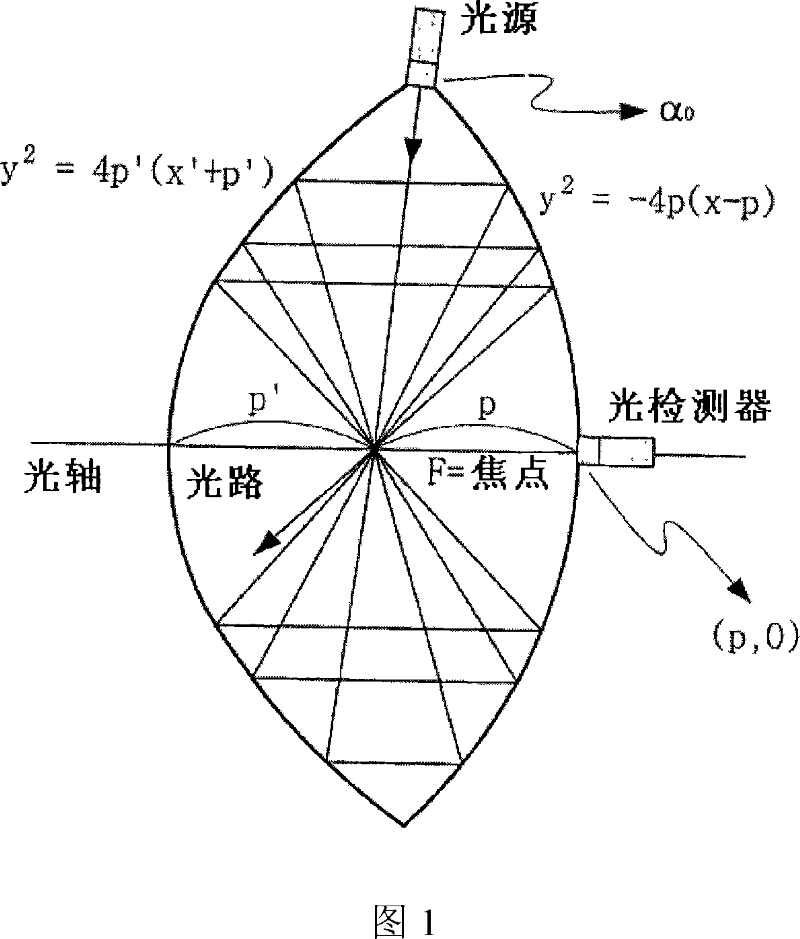
[0028] Figure 1 shows an optical cavity using two quadratic parabolic concave mirrors according to one embodiment of the present invention.

[0029] In a parabolic concave mirror, light incident toward the focal point travels parallel to the optical axis after being reflected by the mirror, and light incident parallel to the optical axis passes through the focus after being reflected by the mirror. Based on the above reflection characteristics of parabolic concave mirrors, as shown in Figure 1, two concave mirrors are arranged opposite to each other, so that the two concave mirrors obtained from two quadratic functions with focal lengths p and p′ are confocal, thereby forming a light cavity. At this point, the light source is at position A 0 And towards the focal point, the photodetector is located at the optical axis (p,0) along the -x direction.

[0030] The light emitt...


PUM


Abstract

Disclosed are an optical cavity and a gas cell fabricated by using the same. The optical cavity is the most important element of the gas cell, which measures density of gas using light absorption characteristics of the gas. The gas cell includes two quadratic parabolic concave mirrors, which share a focus and an optical axis. Light incident toward the focus is reflected from the two quadratic parabolic concave mirrors so that the light may travel in parallel to the optical axis and the light incident in parallel to the optical axis may pass through the focus while being reflected from the two quadratic parabolic concave mirrors. The optical cavity includes two quadratic parabolic concave mirrors, which are aligned in opposition to each other with different focus lengths such that they share the focus using the reflection characteristics thereof.

Description

technical field [0001] The invention relates to a method of manufacturing a gas cell, the most important element of a gas density measuring device using NDIR (non-dispersive infrared) technology. More specifically, the present invention relates to a method of manufacturing a gas chamber with an optical cavity, wherein the gas chamber is suitable for various applications and has a simple geometry for easy analysis of optical paths; and a method of manufacturing a gas chamber using the gas chamber sensor method. Background technique [0002] As public attention to the atmospheric environment increases, technologies for preventing accidents by accurately detecting toxic gases contained in the atmosphere or produced by factories have become increasingly important. In this field, it is necessary to provide a portable gas sensor suitable for a narrow space or a small-sized gas sensor as well as a large-sized gas sensor. To this end, many efforts have been made in order to manufa...

Claims


Application Information

Patent Timeline
Patent Type & Authority Applications(China)
IPC IPC(8): G01N21/61
CPCG01N21/3504G01N21/031G01N21/61G01N21/359
Inventor 李承焕朴正翼
Owner ELT
Why Eureka
Try Eureka