Signal transmission method based on irs phase rotation to maximize received signal-to-noise ratio

A receiving signal-to-noise ratio and phase rotation technology, which is applied in transmitter monitoring, space transmit diversity, transmission monitoring, etc., can solve problems such as low complexity and low complexity, and achieve low complexity, stable convergence, and optimal performance effect

Active Publication Date: 2021-09-24
UNIV OF ELECTRONICS SCI & TECH OF CHINA
View PDF9 Cites 0 Cited by
  • Summary
  • Abstract
  • Description
  • Claims
  • Application Information

AI Technical Summary

Problems solved by technology

[0004] Aiming at the problem that the optimal phase rotation cannot be stably obtained with a low-complexity algorithm in the IRS-MISO system, the present invention provides a low-complexity Optimal Iteration (Optimal Iteration, OI) calculation, which has a low complexity , at the same time, it can stably obtain the optimal phase rotation design, and has a very flexible usage scenario

Method used


Image

  • Signal transmission method based on irs phase rotation to maximize received signal-to-noise ratio
  • Signal transmission method based on irs phase rotation to maximize received signal-to-noise ratio
  • Signal transmission method based on irs phase rotation to maximize received signal-to-noise ratio

Examples


Embodiment Construction

[0025] Specific embodiments of the present invention will be described below in conjunction with the accompanying drawings, so that those skilled in the art can better understand the present invention. It should be specially reminded that in the following description, when detailed descriptions of known functions and designs may dilute the main content of the present invention, these descriptions are omitted here.

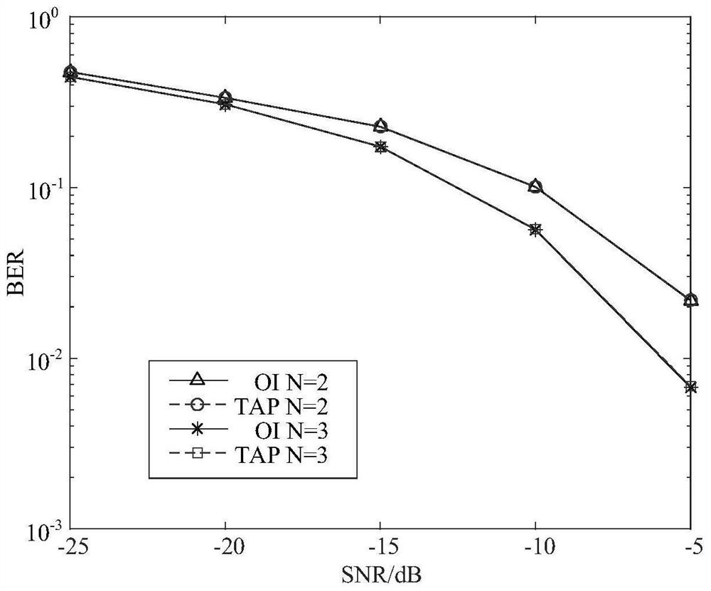
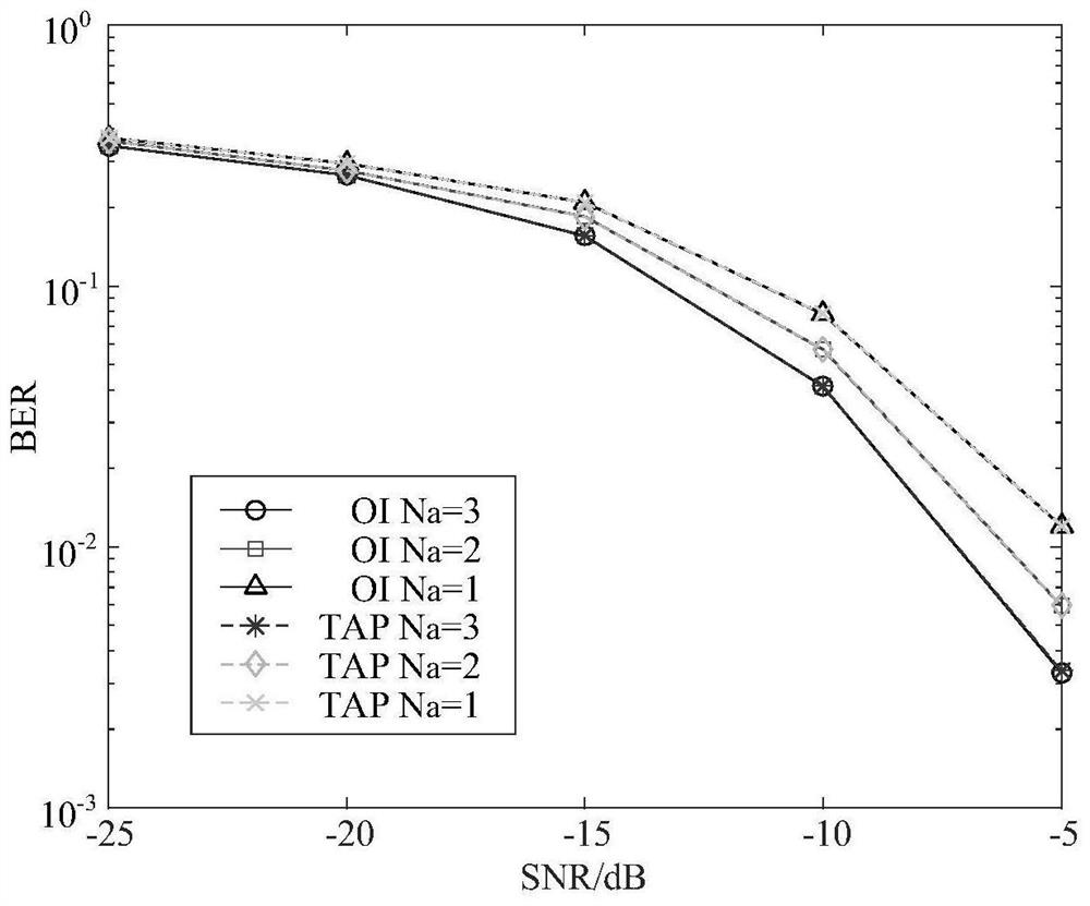
[0026] Since the current research has not fully mentioned the method of traversing all the possible phase shifts (TAP) to obtain the optimal phase rotation angle, the problem model based on maximizing the receiving signal-to-noise ratio will be given later, and the TAP scheme will be introduced and its complexity.

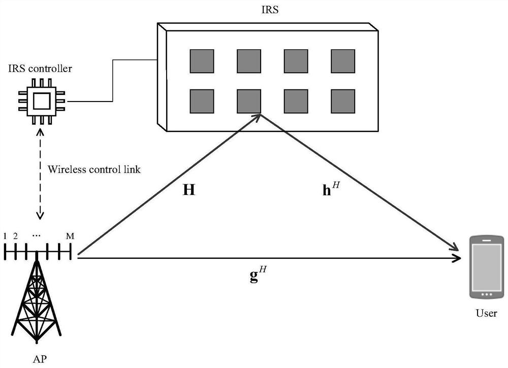
[0027] In order to describe the present invention better, the terminology and system structure used in the technical solution of the present invention are introduced first.

[0028] MISO: MISO technology refers to the use of multiple transmitting anten...


PUM


Abstract

The present invention provides a signal transmission method based on the IRS phase rotation angle that maximizes the received signal-to-noise ratio, including the steps: the sender modulates the information bits to obtain a modulated signal; The principle of signal-to-noise ratio generates the optimal phase rotation angle and adjusts the phase angle of the smart reflector through the controller; the sender uses the optimal beamforming scheme to process the modulated signal, and then transmits it through all transmitting antennas. In IRS-assisted MISO system transmission, compared with the traditional phase rotation design scheme, the present invention provides a new iterative calculation method for optimally maximizing the receiving signal-to-noise ratio, which can stably converge to the global optimal solution, and has Lower computational complexity. In practical applications, only certain phase units on the IRS may be adjustable, and this method can still find the optimal solution in this case, which has good flexibility.

Description

technical field [0001] The present invention relates to wireless communication physical layer security technology, in particular to Multiple Input Single Output (Multiple Input Single Output, MISO) technology and Intelligent Reflecting Surface (Intelligent Reflecting Surface, IRS) technology. Background technique [0002] As a 6G wireless transmission solution that improves spectrum and energy efficiency, the intelligent reflector IRS has multiple passive reflection units that can reflect and adjust the phase of the signal. Compared with the traditional scheme of increasing the antenna array, the IRS technique can provide similar multipath gain while avoiding expensive hardware requirements. At the same time, the cheap IRS has flexible usage scenarios and can be covered on the surface of outdoor buildings and indoor walls. Therefore, under the trend of pursuing high spectrum efficiency, high energy efficiency and low bit error rate in the future, IRS will become a wireless ...

Claims


Application Information

Patent Timeline
Patent Type & Authority Patents(China)
IPC IPC(8): H04B17/12H04B17/336H04B7/06H04B7/08
CPCH04B17/12H04B17/336H04B7/0617H04B7/086H04B7/04013
Inventor 牛鸿雷霞肖悦
Owner UNIV OF ELECTRONICS SCI & TECH OF CHINA
Why Eureka
Try Eureka