Magnetic field induction game

A magnetic field induction and joystick technology, applied in the field of joysticks, can solve the problems of high price and unfavorable product popularization, and achieve the effect of sensitive response and low cost

Inactive Publication Date: 2007-10-03
IND TECH RES INST
View PDF1 Cites 27 Cited by
  • Summary
  • Abstract
  • Description
  • Claims
  • Application Information

AI Technical Summary

Problems solved by technology

[0003] U.S. patent document US005850142 discloses a magnetic field induction joystick, which combines the spherical joint of the joystick and the induction magnet with a special magnetic sensing material. Although its...

Method used


Image

  • Magnetic field induction game
  • Magnetic field induction game
  • Magnetic field induction game

Examples


Embodiment Construction

[0031] In order to enable your review committee to have a further understanding and understanding of the characteristics, purpose and functions of the present invention, the relevant detailed structure and design concept of the device of the present invention will be explained below, so that the review committee can understand the present invention The characteristics are described as follows in conjunction with the illustrations:

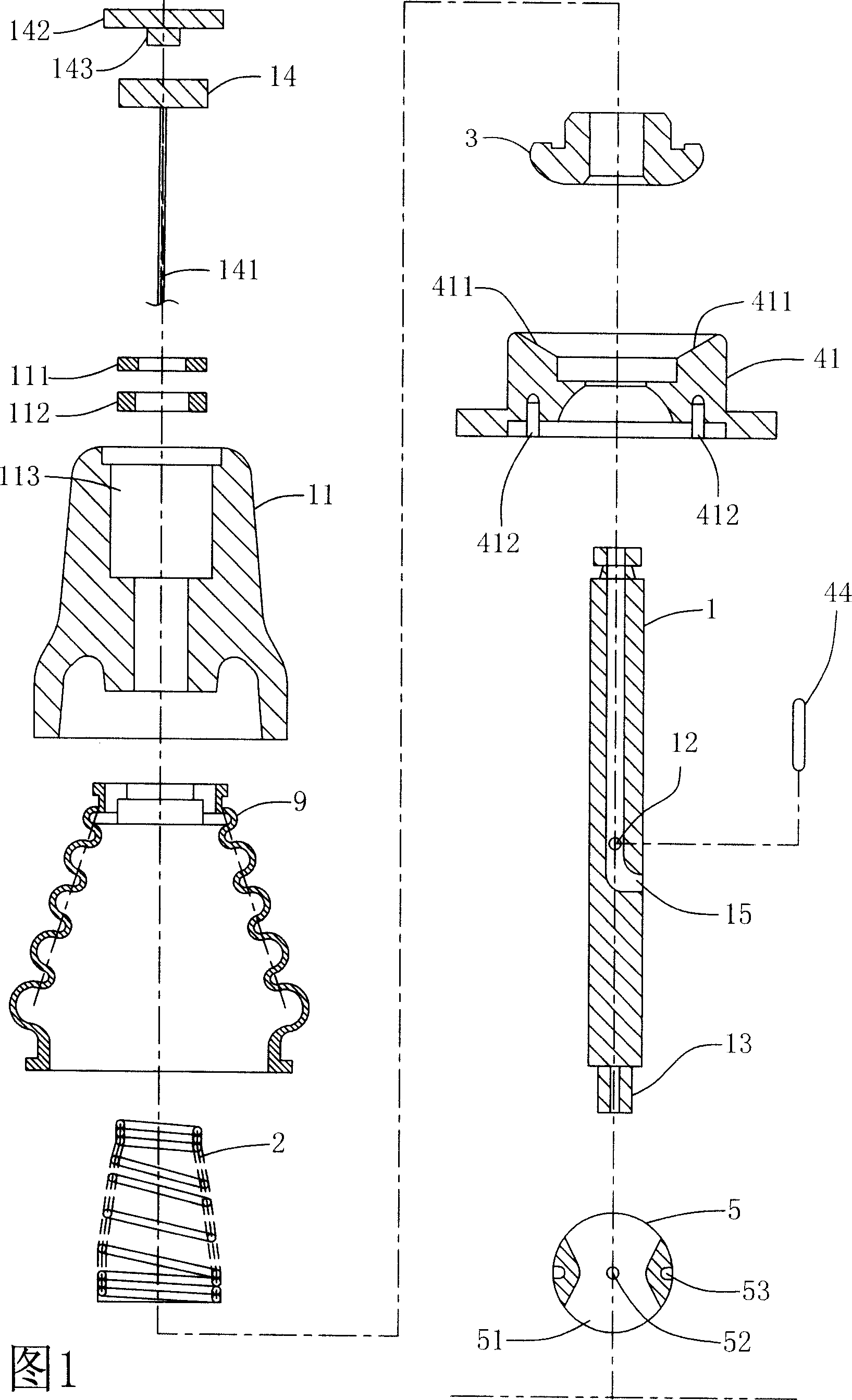
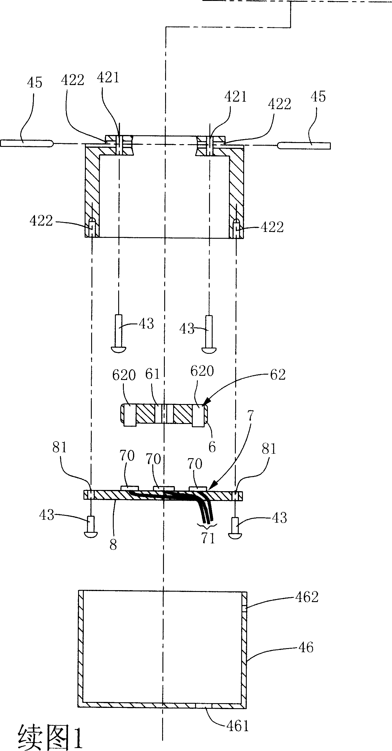
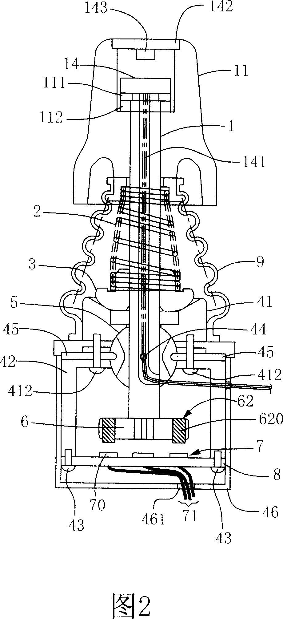
[0032] Please refer to FIG. 1 and FIG. 2 , wherein FIG. 1 (two pages in total) is an exploded view of the first preferred embodiment of the present invention, and FIG. 2 is an assembled view of FIG. 1 . As shown in the above diagram, in this embodiment, the present invention provides a magnetic field induction joystick, which mainly includes: a joystick 1, a spring 2, a spring base 3, a base 4, A pivot joint 5 , a carrier plate 6 and a magnetic field sensing module 7 . Wherein said joystick 1 is a hollow pipe body, and a handle 11 is provided on i...


PUM


Abstract

The present invention relates to a magnetic field induction type game rod. It includes the following several portions: a control rod, a spring, a spring base, a base seat, a trochoid, a bearing plate and a magnetic field induction module. Said invention also provides the connection mode of all above-mentioned portion, and also provides the working principle of said magnetic field induction type game rod and its concrete operation method.

Description

technical field [0001] The invention relates to a joystick, in particular to a magnetic field induction joystick. Background technique [0002] The joystick is a convenient manual remote control device and a position signal generator, which can be used in electronic game consoles, drone remote controls or electric wheelchairs, etc. At present, the position signal generation methods of the joystick can be divided into two types: contact type and non-contact type, and the non-contact type joystick has the advantages of better durability and less failure. Early non-contact joysticks used small coils to sense changes in current signals, but in recent years, magnetic field induction is the main way, which uses induction magnets with magnetic field sensors so that when the position of the joystick changes, the magnetic field sensor Different current or voltage signals will be generated due to sensing different magnetic field strengths. [0003] U.S. patent document US005850142 d...

Claims


Application Information

Patent Timeline
IPC IPC(8): G05G1/04G01R33/07A63F13/02A63F13/92
Inventor 古焕隆
Owner IND TECH RES INST
Why Eureka
Try Eureka