Discharge lamp device and illumination instrument

A technology for discharge lamps and lighting devices, which is applied to parts, lighting devices, circuit layouts and other directions of gas discharge lamps, can solve problems such as thermal degradation of electronic parts and inability to ensure sufficient storage space, and achieves temperature rise suppression and luminous efficiency suppression. The effect of reducing and maintaining miniaturization

Inactive Publication Date: 2007-10-03
TOSHIBA LIGHTING & TECH CORP
View PDF1 Cites 8 Cited by
  • Summary
  • Abstract
  • Description
  • Claims
  • Application Information

AI Technical Summary

Problems solved by technology

On the other hand, in general, sufficient storage space cannot be secured near the periphery of the circular body, so the lighting device is also accommodated near the center of the body.
[0008] Therefore, the luminous tube, which tends to become high temperature, is relatively close to the lighting device, which may cause thermal degradation of electronic components and the like used in the lighting device.

Method used


Image

  • Discharge lamp device and illumination instrument
  • Discharge lamp device and illumination instrument
  • Discharge lamp device and illumination instrument

Examples


Embodiment Construction

[0087] Hereinafter, an embodiment of a discharge lamp device and a lighting fixture according to the present invention will be described with reference to the drawings.

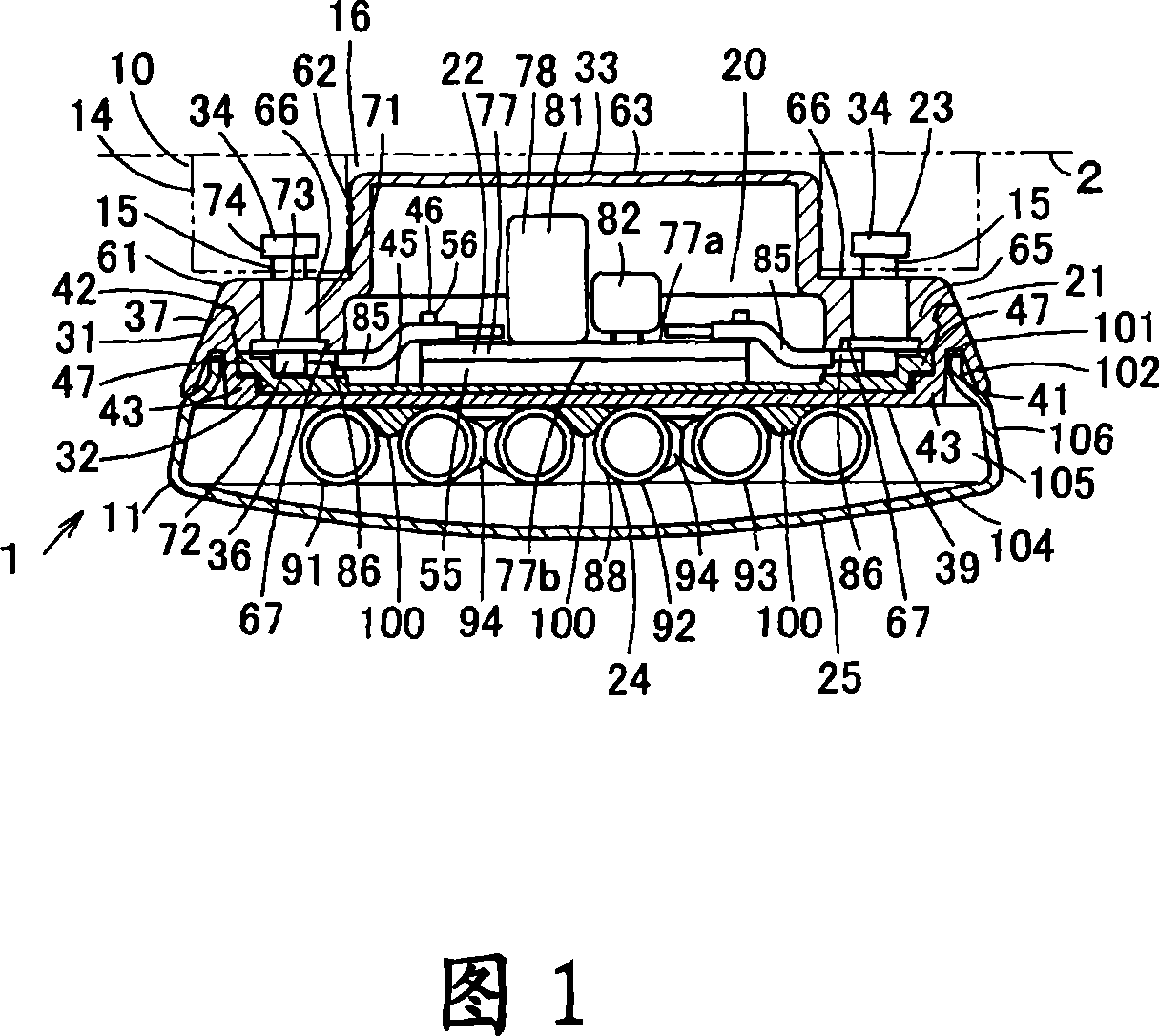
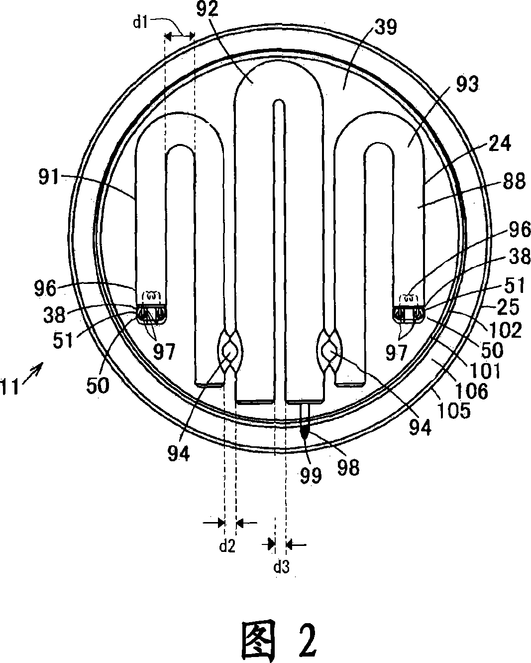
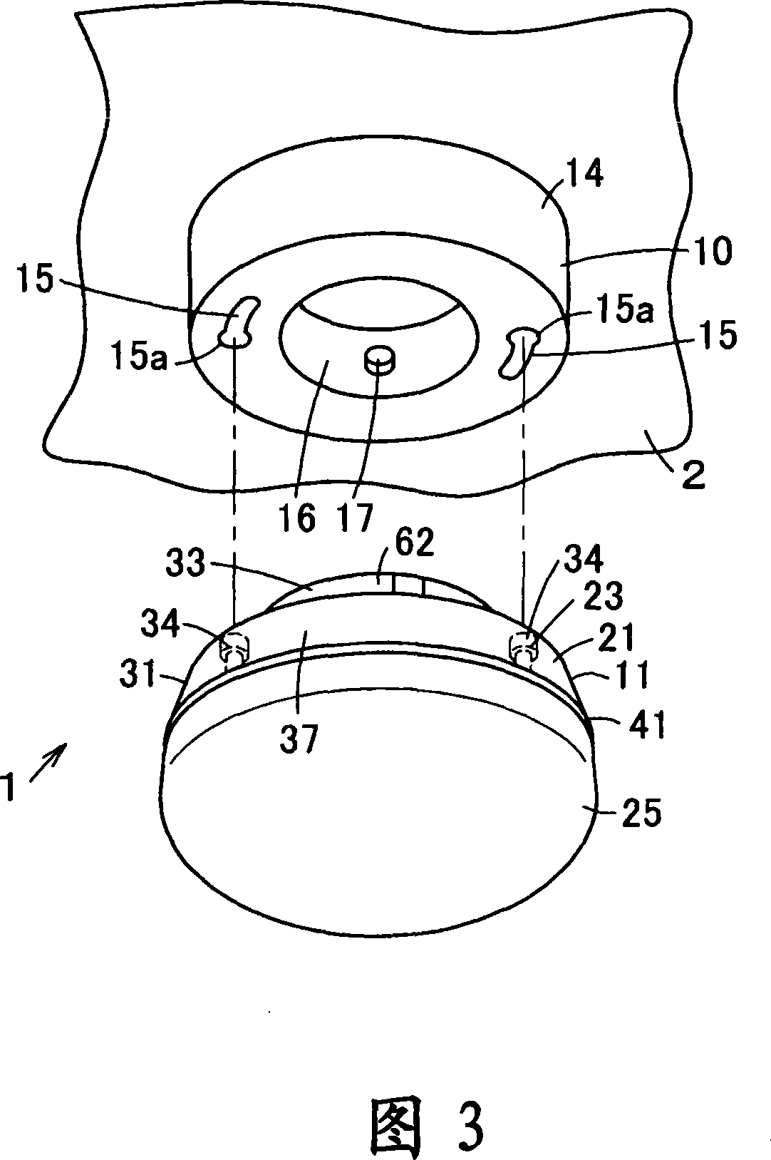
[0088]Fig. 1 is a longitudinal sectional view showing an embodiment of a lighting fixture having a discharge lamp device according to the present invention, and Fig. 2 is a transverse sectional view of the lighting fixture. 3 is a perspective view of a state in which the discharge lamp device of the lighting fixture is detached from the socket device. Fig. 4 is an exploded perspective view of the discharge lamp device. Fig. 5 is a side view of the discharge lamp device. Fig. 6 is a perspective view of the partition plate of the discharge lamp device viewed from the lower surface side. Fig. 7 is a perspective view showing a manufacturing procedure of the discharge lamp device.

[0089] In Fig. 1 to Fig. 3, 1 is a lighting fixture, and the lighting fixture 1 is, for example, a lighting fixture that is direct...


PUM


Abstract

The invention provides a discharge lamp device and light fixtures, which will not relatively largen the almost round body, and separate the electrode easy to be high temperature discharge lamp device from lighting device, therefore the surrounding temperature of the lighting device can be restrained. The discharge lamp device comprises an almost round body (21); lighting device (22) in the certre of the one side of the body (21); and discharge lamp (24). The discharge lamp (24) comprises several straight tubes parallel to each other on the surface; interlink part for connecting with the end of the straight tube, and discharge electrode (96) enveloped on the end of the most outboard straight tube. The granularity d1 of the most outboard straight tube and straight tube adjacent to the above straight tube is more than the granularity between the other straight tubes, and the discharge lamp is formed in the style of wholly roundness fit for body (21), and is set on the other side of the body (21).

Description

technical field [0001] The invention relates to a discharge lamp device and a lighting appliance including a discharge lamp and a lighting device. Background technique [0002] Conventionally, a fluorescent lamp device including an integrated fluorescent lamp and a lighting device has been used. The fluorescent lamp includes an arc tube having a curved tube; the lighting device lights up the arc tube (for example, refer to Patent Document 1). As the above-mentioned fluorescent lamp device, there is known a flat disc-shaped fluorescent lamp device, that is, in order to obtain a planar light source, a lighting device is accommodated in a flat disc-shaped body, and an upper surface of the body is integrally provided with The lamp base part, and along the lower surface of the main body, a light-emitting tube bent into a planar shape is arranged. In addition, the lower surface of the main body and the arc tube are covered with a glove (for example, refer to Non-Patent Document ...

Claims


Application Information

Patent Timeline
Patent Type & Authority Applications(China)
IPC IPC(8): H01J61/02H01J61/30H01J61/36F21V17/00F21V19/00F21V23/06F21S4/00F21Y103/37
Inventor 大野铁也
Owner TOSHIBA LIGHTING & TECH CORP
Why Eureka
Try Eureka