
Image encoding apparatus and decoding apparatus

An image and encoding technology, applied in the field of decoding devices for decoding encoded images, can solve problems such as weakness

Inactive Publication Date: 2010-12-08
KK TOSHIBA
View PDF5 Cites 0 Cited by
  • Summary
  • Abstract
  • Description
  • Claims
  • Application Information

AI Technical Summary

Problems solved by technology

Given that the international standard MPEG-4AVC / H.264 provides a 5-tap spatial filter to remove block noise, the above system is weak compared to that of MPEG-4 AVC / H.264

Method used


Image

  • Image encoding apparatus and decoding apparatus
  • Image encoding apparatus and decoding apparatus
  • Image encoding apparatus and decoding apparatus

Examples


Embodiment Construction

[0016] An image encoding device related to an embodiment will now be described in detail with reference to the attached drawings.

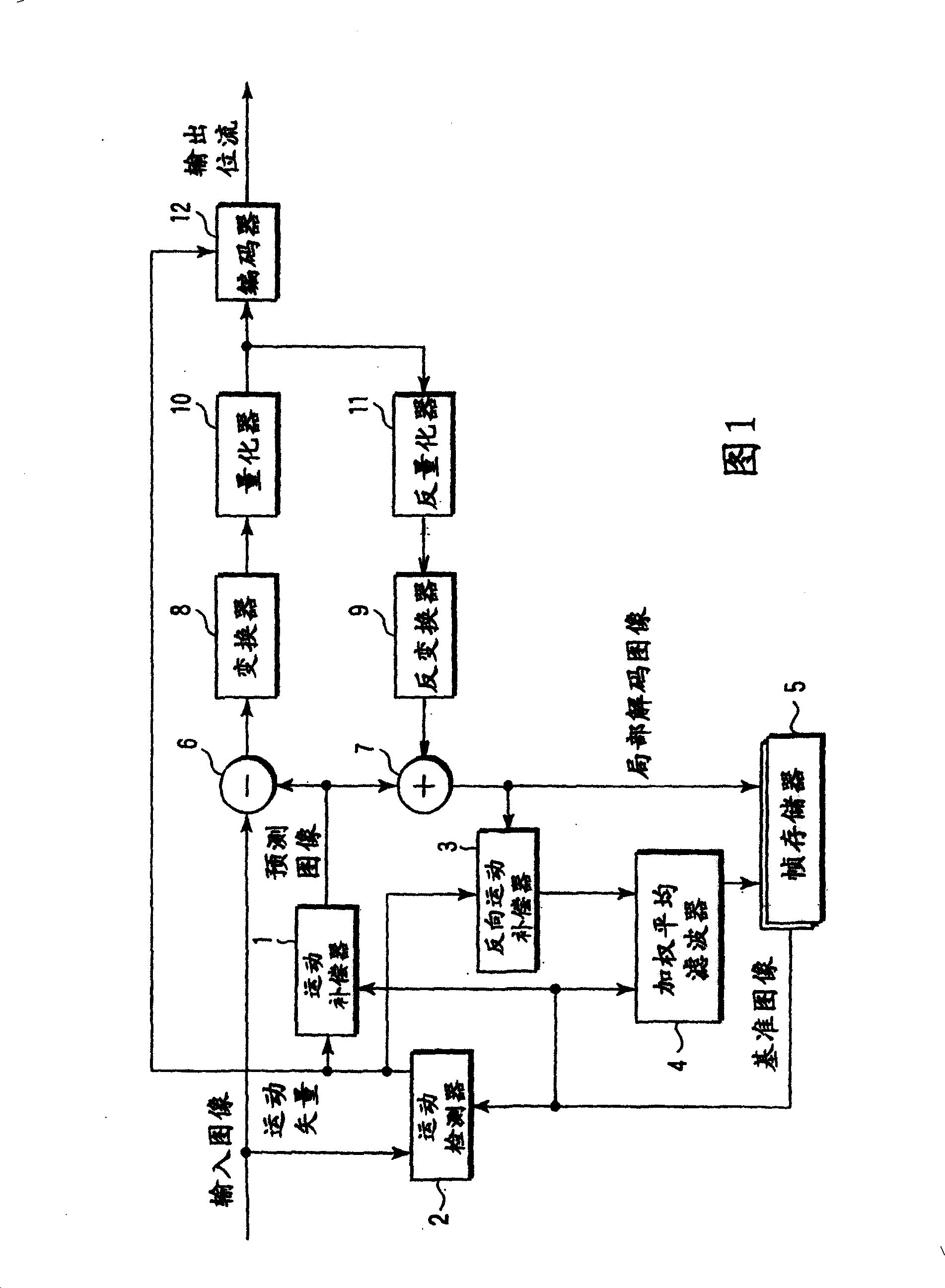
[0017] figure 1 The video coding apparatus shown in includes a motion compensator 1, a motion estimator 2, an inverse motion compensator 3, a weighted average filter 4, a frame memory 5, a subtractor 6, an adder 7, a converter 8, and an inverse transform device 9. Quantizer 10, Inverse Quantizer 11 and Entropy Coder 12.

[0018] The motion compensator 1 is connected to the motion detector 2 and the frame memory 5 and is configured to generate a predicted image from a motion vector of the motion detector 2 and a reference image of the frame memory 5 . The motion detector 2 is configured to receive an input image (original image) and a reference image of the frame memory 5 and to detect a motion vector from these images.

[0019] The inverse motion compensator 3 is connected to the motion detector 2 and the frame memory 5, and uses the motion vec...


PUM


Abstract

An encoding apparatus disclosed by the invention includes a motion compensator to motion-compensate a reference image to generate a predictive image of an input image, a subtracter to generate a differential signal between the input image and the predictive image, an encoder to encode the differential signal to generate encoded information, a local decoder to local-decode the encoded information to generate a local-decoded differential image, a filter to perform a filtering process of a temporal direction between the local-decoded differential image and the predictive image, an inverse motioncompensator to motion-compensate the image provided by the filtering process in an inverse direction with respect to motion compensation of the motion compensator to generate an inverse predictive image, and an updating unit configured to update the reference image by the inverse predictive image.

Description

technical field [0001] The invention relates to a video encoding device for encoding video images and a decoding device for decoding encoded images. Background technique [0002] In video coding, inter-frame motion compensation using redundancy between frames is used. For example, JP-A7-288719 (KOKAI) discloses a technique of removing encoding distortion of a reference image by temporal filtering between a reference frame and an encoding frame. configured in image 3 displayed in . When encoding frame P3, for example, frame P3 is filtered with a time-direction low-pass filter with motion compensation using picture I0 used as a reference frame for frame P3 before it is stored as a reference image in the frame memory, in order to reduce the encoding distortion. If the distortion-reduced reference frame is thus used to code each of the frames B1, B2, P6, B4 and B5, the coding efficiency is improved. [0003] However, when viewed as a filter, this coding distortion removal s...

Claims


Application Information

Patent Timeline
Patent Type & Authority Patents(China)
IPC IPC(8): H04N7/50H04N7/26H04N7/30H04N19/117H03M7/36H04N19/136H04N19/137H04N19/139H04N19/196H04N19/50H04N19/503H04N19/51H04N19/573H04N19/61H04N19/625H04N19/80H04N19/82H04N19/91
CPCH04N19/00781H04N19/00587H04N19/00896H04N19/51H04N19/61H04N19/82H04N19/42
Inventor 儿玉知也
Owner KK TOSHIBA
Features
  • Generate Ideas
  • Intellectual Property
  • Life Sciences
  • Materials
  • Tech Scout
  • Unparalleled Data Quality
  • Higher Quality Content
  • 60% Fewer Hallucinations
Learn More