Forward-reverse switching device for stepless speed changer

A technology of forward and backward, switching devices, applied in the direction of transmission, transmission parts, transmission control, etc., can solve the problems of large friction loss, unoptimized torque transmission, complicated hydraulic control, etc., to reduce processing costs, reduce Small friction loss, simple hydraulic control effect

Inactive Publication Date: 2007-10-03
DAIHATSU MOTOR CO LTD +1
View PDF2 Cites 8 Cited by
  • Summary
  • Abstract
  • Description
  • Claims
  • Application Information

AI Technical Summary

Problems solved by technology

[0006] As described above, the clutch drum 110 and the input shaft 102, which constitute the hydraulic actuator for connecting the direct drive clutch 108, rotate integrally. Therefore, it is necessary to provide a seal ring 117 for preventing oil leakage in the supply oil passage for supplying oil to the clutch drum 110. Therefore, there is a problem of large friction loss
In addition, centrifugal hydraulic pressure is generated in the hydraulic pressure chamber of the clutch drum 110 by the centrifugal force accompanyin

Method used


Image

  • Forward-reverse switching device for stepless speed changer
  • Forward-reverse switching device for stepless speed changer
  • Forward-reverse switching device for stepless speed changer

Examples


Example Embodiment

[0054] Example 1

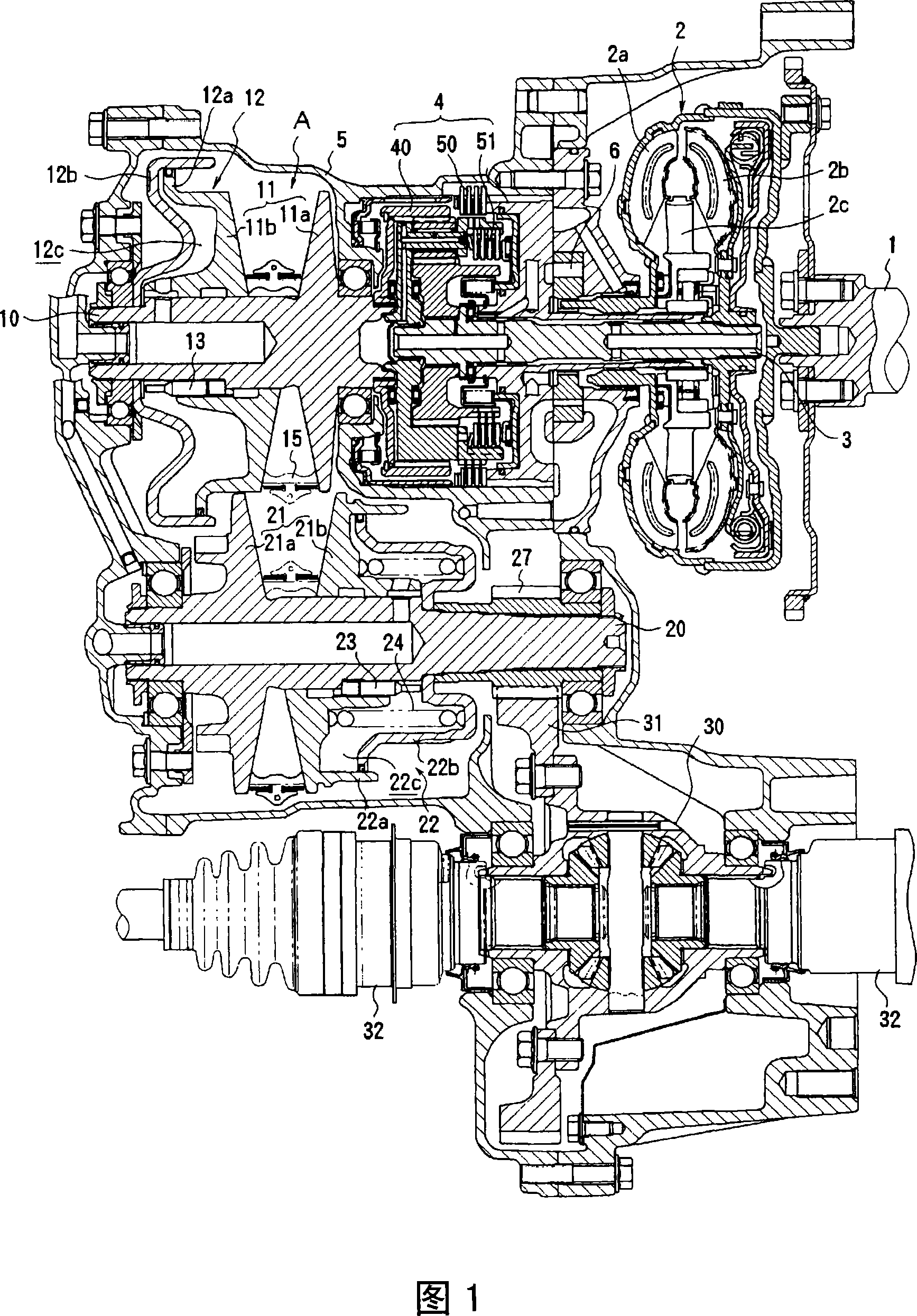
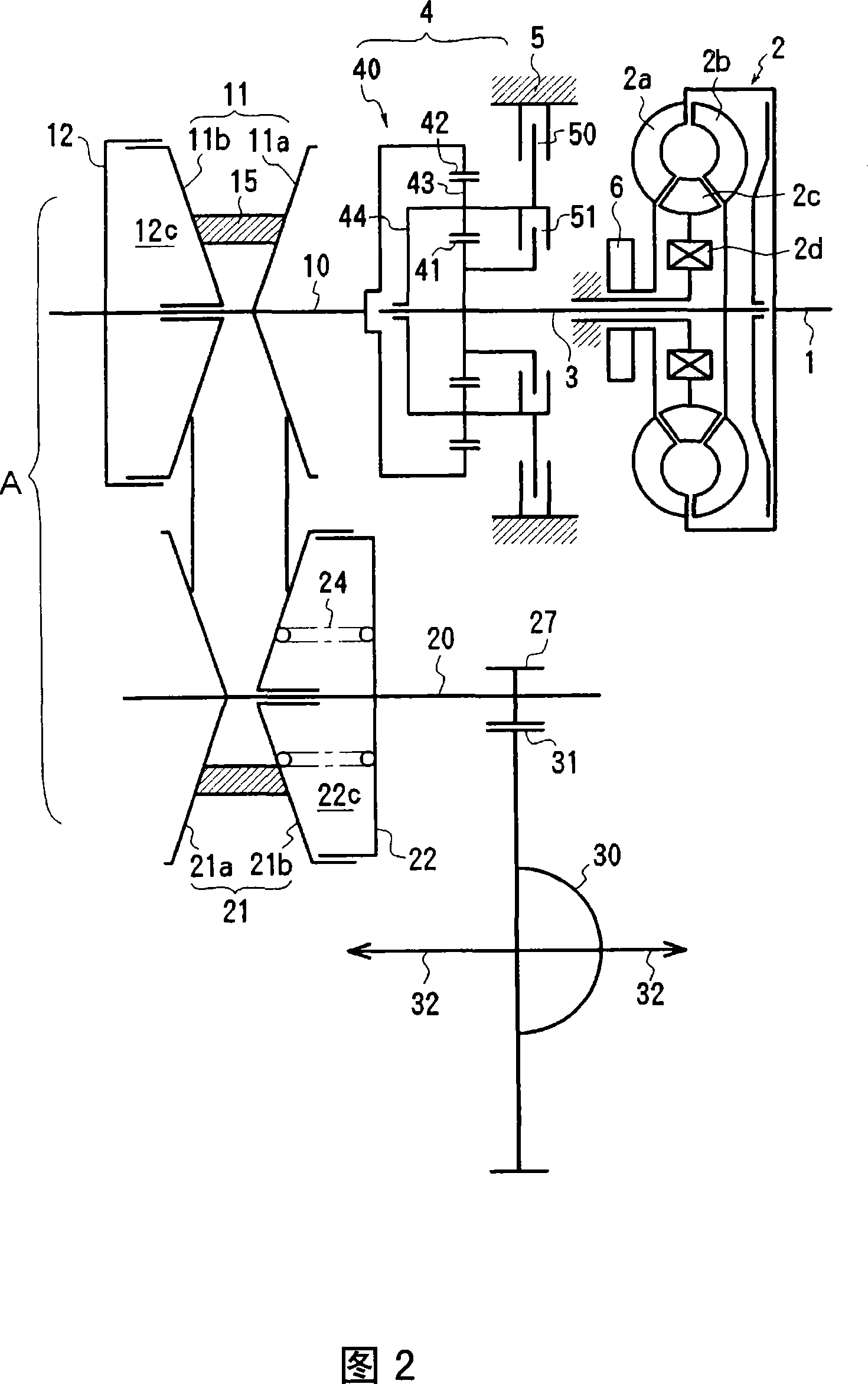
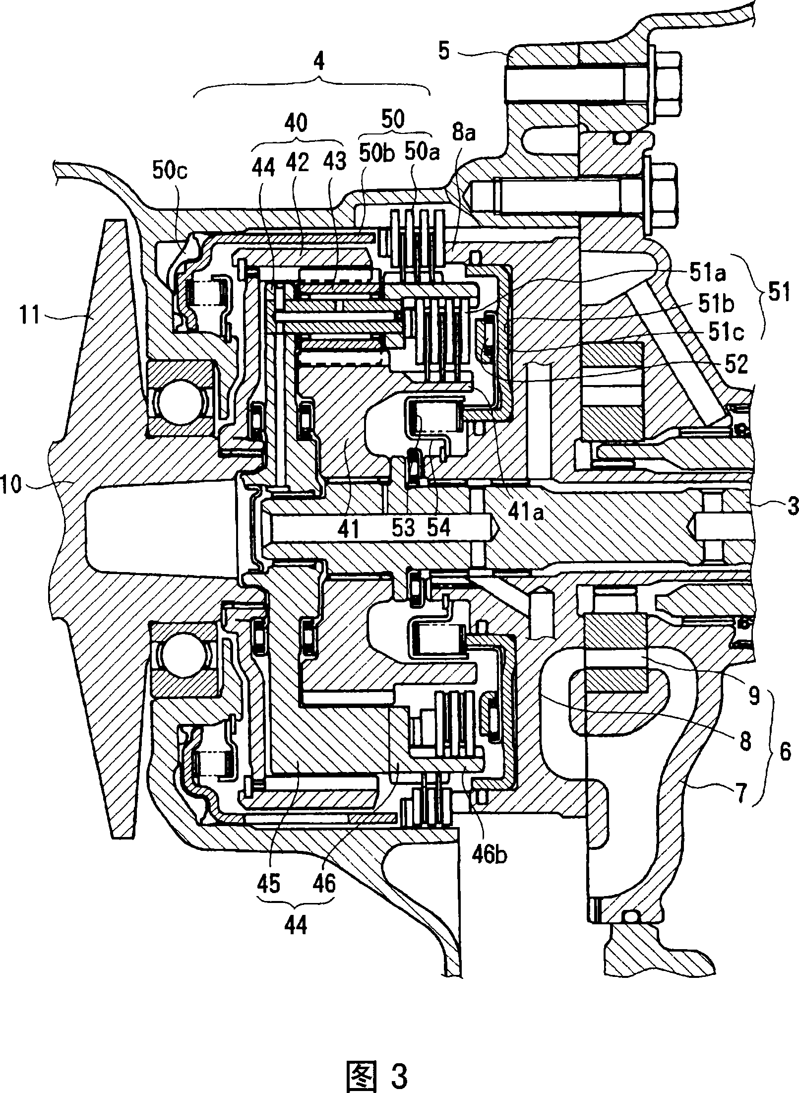
[0055] Figures 1 to 3 show an example of the continuously variable transmission of the present invention.

[0056] The continuously variable transmission of this embodiment is an FF horizontal type automobile transmission, and roughly includes: an input shaft 3 driven by a torque converter 2 under the action of an engine output shaft 1; The forward and backward switching device 4 transmitted to the drive shaft 10; the continuously variable transmission device A composed of the drive wheel 11, the driven wheel 21, and the V belt 15 wound between the two wheels; the power of the driven shaft 20 is directed to the output shaft 32 transfer of the differential device 30 and so on. The input shaft 3 and the drive shaft 10 are arranged on the same axis, and the driven shaft 20 and the output shaft 32 of the differential device 30 are arranged in parallel and non-coaxially with respect to the input shaft 3. Therefore, the continuously variable transmission is formed as ...

Example Embodiment

[0079] Example 2

[0080] Fig. 7 shows a second embodiment of the forward and backward switching device of the present invention. In FIG. 7, the same parts as those in the first embodiment are denoted by the same symbols, and repeated descriptions are omitted. In addition, the structure other than the forward-reverse switching device is the same as in Patent Document 2.

[0081] The planetary gear mechanism 40' is formed in a double pinion system, and the planetary carrier 44 supports two types of pinion gears 43A and 43B. One pinion gear 43A meshes with the ring gear 42 and the pinion gear 43B, and the other pinion gear 43B meshes with the pinion gear 43A and the sun gear 41. The sun gear 41 is combined with the input shaft 3, and the planetary gear carrier 44 is combined with the drive shaft 10. The reverse brake 50 is provided between the ring gear 42 and the transmission housing 5, and the hydraulic piston 50 b for operating the reverse brake 50 is arranged in the transmission...


PUM


Abstract

A forward-reverse switching device for a stepless speed changer, in which friction loss is reduced by installing a hydraulic actuator of a direct connection clutch on a stationary member, and which is simple in structure and small in size. [MEANS FOR SOLVING PROBLEM] A forward-reverse switching device for a stepless speed changer has a planetary gear mechanism (40), a reverse brake (50), and a direct connection clutch (51), where the reverse brake (50) is installed between a carrier (44) and a speed changer case (5) and where the direct connection clutch (51) is installed between the carrier (44) and a sun gear (41). The sun gear (41) is connected to an input shaft (3), and a ring gear (42) is connected to a drive pulley (11). Hydraulic actuators (51b, 51c) for engaging the direct connection clutch (51) are arranged on an oil pump cover (8) fixed to the speed changer case (5). A thrust bearing (52) is provided between a hydraulic piston (51c) and a clutch disc (51a).

Description

technical field [0001] The present invention relates to a forward-backward switching device of a continuously variable transmission, in particular to a forward-backward switching device equipped with a planetary gear mechanism, a reverse brake and a direct transmission clutch. Background technique [0002] Patent Document 1 discloses a continuously variable transmission having a forward and reverse switching device, a belt type continuously variable transmission and a differential device, wherein the forward and reverse switching device has a single pinion type planetary gear mechanism , and has a reverse brake that connects the sun gear of the planetary gear mechanism to the input side, connects the ring gear to the output side, and locks the planetary carrier with respect to the housing, and a direct transmission that connects the planetary carrier to the sun gear. clutch. When driving forward, by connecting the reverse brake and releasing the direct drive clutch, the dri...

Claims


Application Information

Patent Timeline
IPC IPC(8): F16H57/02F16H3/60F16H37/02F16H57/08
CPCF16H37/027F16H37/022F16H63/3026F16H3/60F16H37/02
Inventor 岛本雅夫羽渊良司高原秀明
Owner DAIHATSU MOTOR CO LTD
Why Eureka
Try Eureka