
Ocular fundus observing device

By using a fixed sight target and a projection optical system in a fundus observation device, the problem of fundus image quality degradation in the prior art is solved, and efficient image acquisition of a desired position of the fundus is achieved.

Active Publication Date: 2007-10-10
KK TOPCON
View PDF4 Cites 10 Cited by
  • Summary
  • Abstract
  • Description
  • Claims
  • Application Information

AI Technical Summary

Problems solved by technology

[0038] However, it is not easy to fix the line of sight of the subject's eye by arranging the desired position on the fundus near the optical axis of the optical system, and it is not easy to obtain an image of the desired position on the fundus.

Method used


Image

  • Ocular fundus observing device
  • Ocular fundus observing device
  • Ocular fundus observing device

Examples


Embodiment Construction

[0056] Hereinafter, a fundus observation device according to an example of an embodiment of the present invention will be described in detail with reference to the drawings. 11 and 12 are assigned the same symbols as those in the prior art.

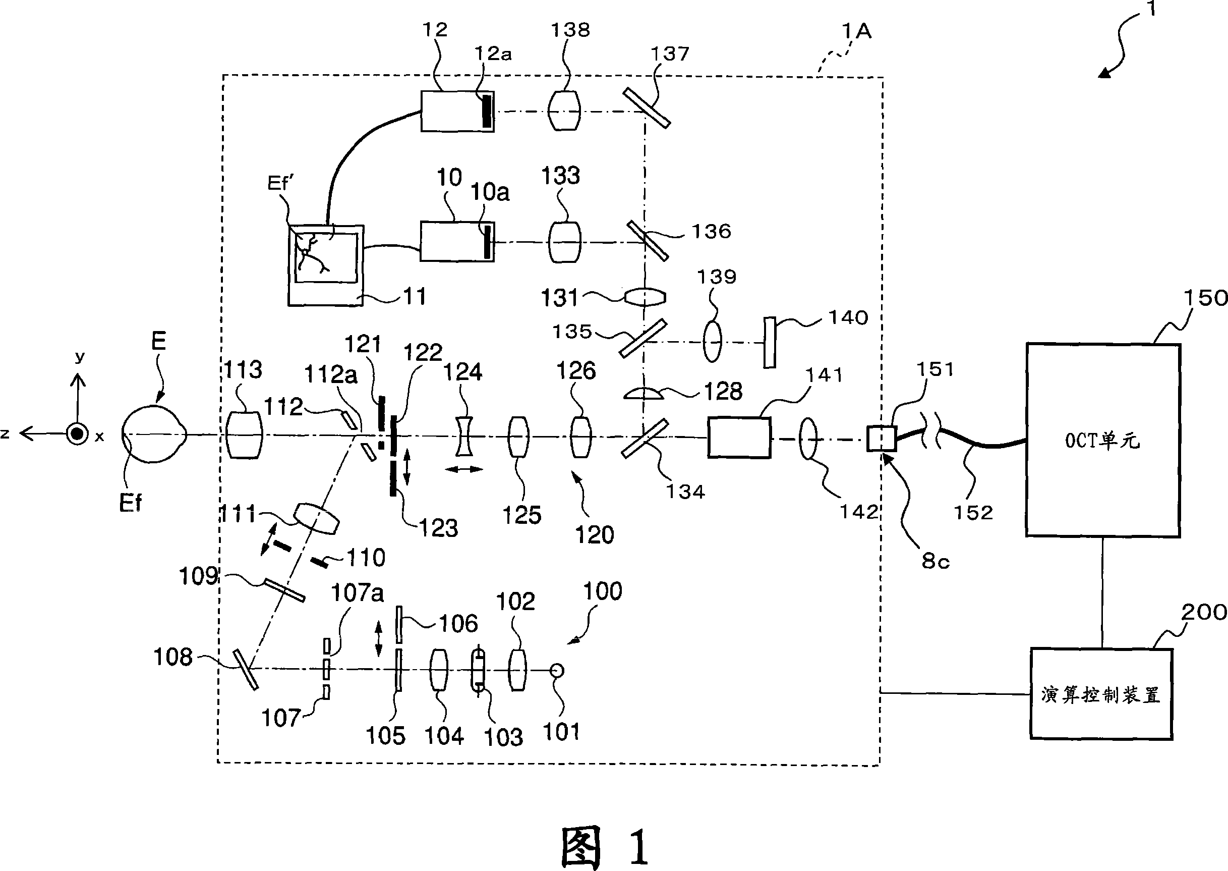
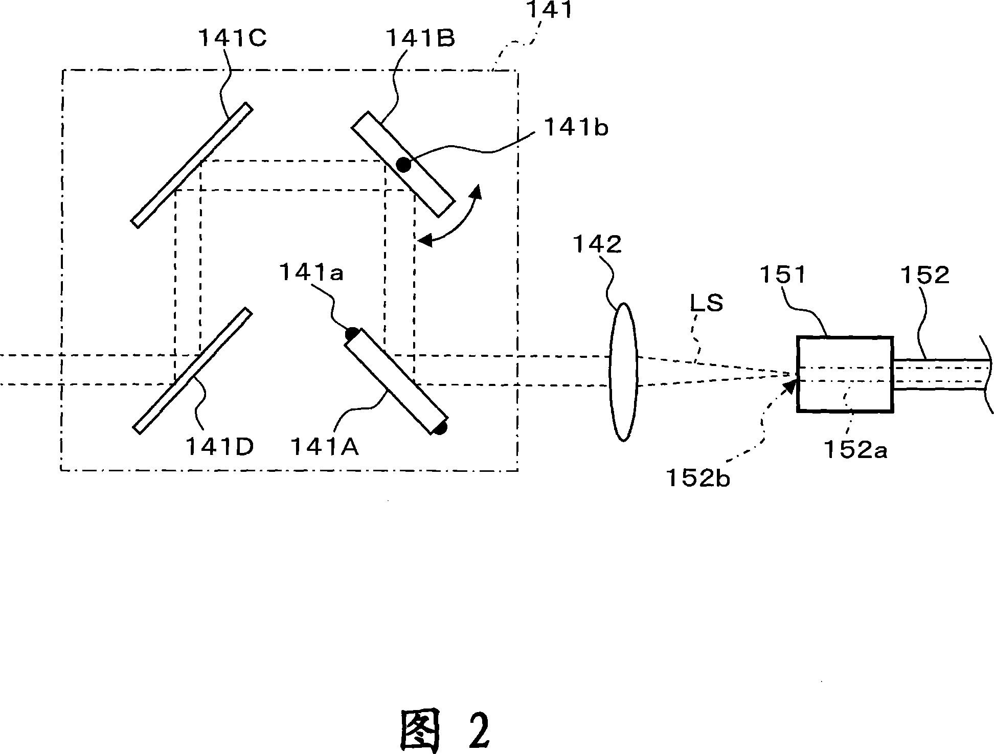
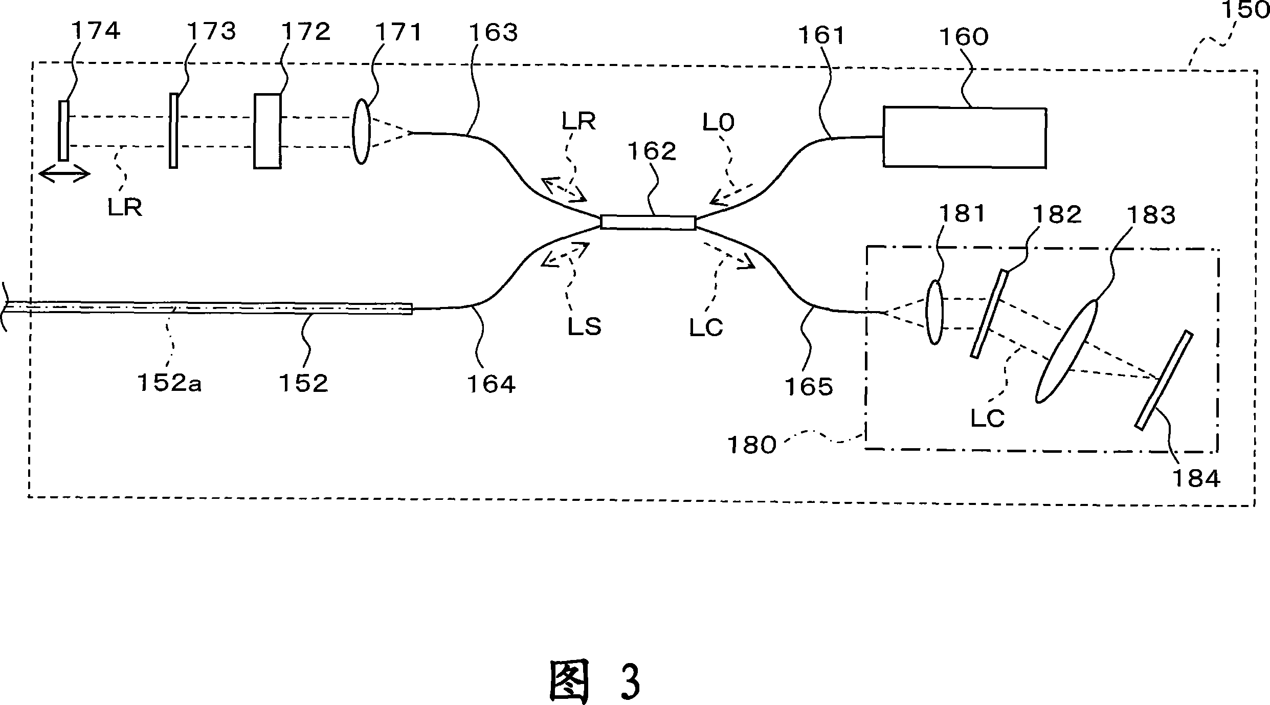
[0057] First, the configuration of the fundus observation device according to the present embodiment will be described with reference to FIGS. 1 to 7 . FIG. 1 shows an example of the overall configuration of a fundus observation device 1 according to this embodiment. FIG. 2 shows the configuration of the scanning unit 141 in the fundus camera unit 1A. FIG. 3 shows the structure of the OCT unit 150 . FIG. 4 shows an example of the hardware configuration of the arithmetic control device 200 . FIG. 5 shows an example of the configuration of the control system of the fundus observation device 1 . FIG. 6 shows an example of the configuration of the operation panel 3 a provided in the fundus camera unit 1A. FIG. 7 shows an example of a con...


PUM


Abstract

A LCD (140) is provided for displaying an internal fixation target for fixating an eye (E). A projection optical system (a part of an imaging optical system (120)) is provided for projecting the displayed internal fixation target onto the a fundus oculi (Ef). An image forming part (220) is provided for forming 2-dimensional images (images of fundus oculi) (Ef') of the surface of fundus oculi (Ef). A display part (240A) is provided for displaying images of fundus oculi (Ef). An operation part (240B) is provided for specifying the position of the displayed images of fundus oculi (Ef'). A main controller (211) is provided for changing the projection position of the internal fixation target on the fundus oculi by changing the display position of the fixation target displayed on the LCD (140) based on the specified position specified using the operation part (240B). The image forming part (220) forms tomographic images of the fundus oculi (Ef) with the internal fixation target projected.

Description

technical field [0001] The present invention relates to a fundus observation device for observing the state of the fundus of an eye to be inspected. Background technique [0002] As a fundus observation device, a fundus camera has conventionally been widely used. FIG. 11 shows an example of an external configuration of a conventional conventional fundus camera, and FIG. 12 shows an example of an optical system built therein (for example, refer to Japanese Patent Application Laid-Open No. 2004-350849). In addition, the term "observation" includes at least observation of a captured image of the fundus (in addition, observation of the fundus with the naked eye may also be included). [0003] First, the appearance structure of a conventional fundus camera 1000 will be described with reference to FIG. 11 . The fundus camera 1000 includes a gantry 3 mounted on a base 2 so as to be slidable in front, rear, left, and right directions (horizontal directions). An operation panel an...

Claims


Application Information

Patent Timeline
Patent Type & Authority Applications(China)
IPC IPC(8): A61B3/12A61B3/14G01B9/02
CPCA61B3/102
Inventor 福间康文大塚浩之弓挂和彦冈田浩昭西尾丰
Owner KK TOPCON
Learn More