Method for improving electromagnetic interference of liquid crystal display and time-sequence controller

A timing controller, liquid crystal display technology, applied in static indicators, instruments, etc., can solve problems such as frequency signal increase

Active Publication Date: 2007-10-10
AU OPTRONICS CORP
View PDF0 Cites 21 Cited by
  • Summary
  • Abstract
  • Description
  • Claims
  • Application Information

AI Technical Summary

Problems solved by technology

However, the size of the current display panel is getting larger and larger, which greatly improves the resolution of the display panel, which also increases the frequency s

Method used


Image

  • Method for improving electromagnetic interference of liquid crystal display and time-sequence controller
  • Method for improving electromagnetic interference of liquid crystal display and time-sequence controller
  • Method for improving electromagnetic interference of liquid crystal display and time-sequence controller

Examples


Embodiment Construction

[0037] For a preferred embodiment of the present invention, please refer to the functional block diagram shown in FIG. 5 a , which includes a timing controller 5 and several source drivers 61 , 62 , 63 . In addition, the timing controller 5 is electrically connected to the source drivers 61 , 62 , 63 .

[0038] Figure 5b further shows the internal functional block diagram of the timing controller 5, which includes an internal oscillation frequency signal generation unit 51, a spread spectrum frequency signal unit (Spread Spectrum CLK Unit) 52, a multi-phase frequency signal generation unit (Multi-Phase CLK Generator) 53 . A data processing logic unit 54 , a line buffer unit 55 , a data latch logic unit 56 and a low voltage differential signal receiving unit 57 .

[0039]Both the internal oscillation frequency signal generating unit 51 and the low voltage differential signal receiving unit 57 are electrically connected to the spread spectrum frequency signal unit 52 . The low ...


PUM


Abstract

A method for improving electromagnetic interference of liquid crystal display includes utilizing time sequence controller to provide the first frequency single and the second frequency signal in point to point transistor logic interface of time sequence controller and source electrode actuator, setting phase of the first frequency signal to be different to phase of the second frequency signal, transmitting a numbers of the first image data to source electrode actuator by time sequence controller according to the first frequency signal and transmitting a numbers of the second image data to source electrode actuator according to the second frequency signal.

Description

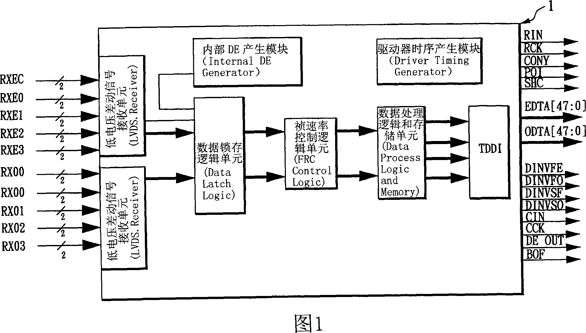
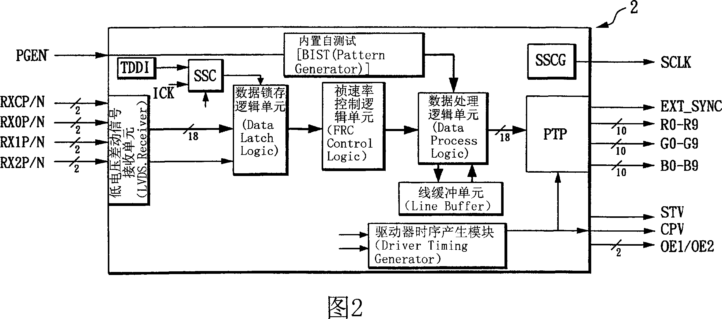
technical field [0001] The invention relates to the technical field of liquid crystal displays, in particular to a method suitable for improving electromagnetic interference of liquid crystal displays. Background technique [0002] Generally speaking, the transistor-transistor logic (TTL) transmission interface between the timing controller and the source driver in a thin-film transistor liquid crystal display (TFT LCD) will cause serious power consumption due to the need for more data buses to transmit images. Power consumption and electromagnetic interference (ElectromagneticInterfering, EMI) phenomenon. [0003] FIG. 1 is a block diagram of a conventional transistor-transistor logic interface transmission timing controller 1 . In order to improve the power consumption and electromagnetic interference between the timing controller 1 and the source driver, the timing controller 1 shown in FIG. 1 transmits image data to the source driver using a dual port transmission metho...

Claims


Application Information

Patent Timeline
IPC IPC(8): G02F1/133G09G3/36
Inventor 易建宇
Owner AU OPTRONICS CORP
Why Eureka
Try Eureka