
Modular panel display device

A flat-panel display device, modular technology, applied to static indicators, televisions, instruments, etc., can solve the problems of high cost, difficulty in moving liquid crystal displays, and reduced efficiency, and achieve the improvement of electromagnetic interference and fast and flexible logistics problems , The effect of reducing maintenance time

Inactive Publication Date: 2007-08-22
PROVIEW TECH SHENZHEN
View PDF0 Cites 10 Cited by
  • Summary
  • Abstract
  • Description
  • Claims
  • Application Information

AI Technical Summary

Problems solved by technology

The liquid crystal display of this structure has at least the following disadvantages: 1. When a certain functional module in the liquid crystal display fails, the user or the maintainer needs to move the entire liquid crystal display from the place of use to the place of maintenance, which makes maintenance extremely inconvenient; Moreover, as the size of LCD monitors becomes larger and larger, it becomes more and more difficult to move the entire LCD monitor, which brings great inconvenience to maintenance.
2. Since the functional modules are directly fixed in the shell, they are easily restricted by the shell during assembly or maintenance, which affects the smooth progress of assembly or maintenance and reduces the efficiency
3. In order to meet different needs, the size of the liquid crystal display can be designed into multiple specifications, and the corresponding housing can also be designed into multiple sizes, so that the functional modules directly installed in the housing also need to be designed into multiple specifications to match the housing. size, making the cost of design and production very high
The support strength provided by the traditional chassis is also insufficient, especially for LCD TVs, because of its emphasis on large size, its center of gravity is getting higher and higher
However, since the traditional chassis is only installed on the bottom edge of the LCD display, if this traditional chassis is installed on an LCD TV with a higher and higher center of gravity, its support strength and reliability are often insufficient

Method used


Image

  • Modular panel display device
  • Modular panel display device
  • Modular panel display device

Examples


Embodiment Construction

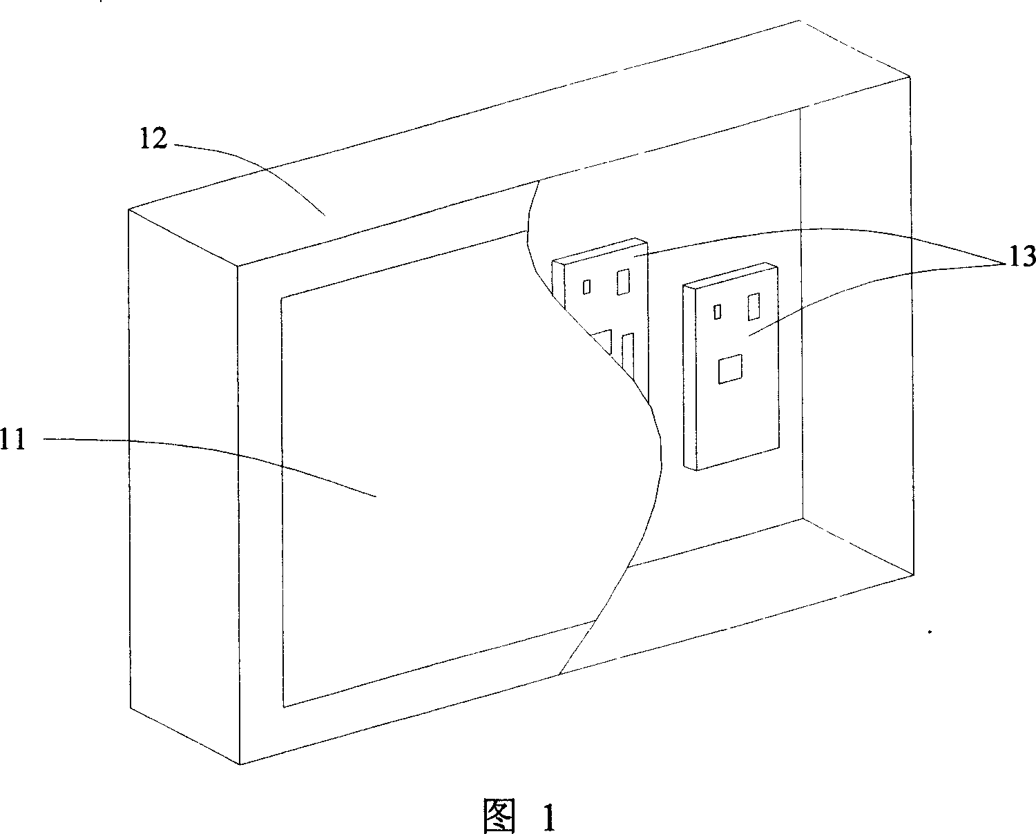
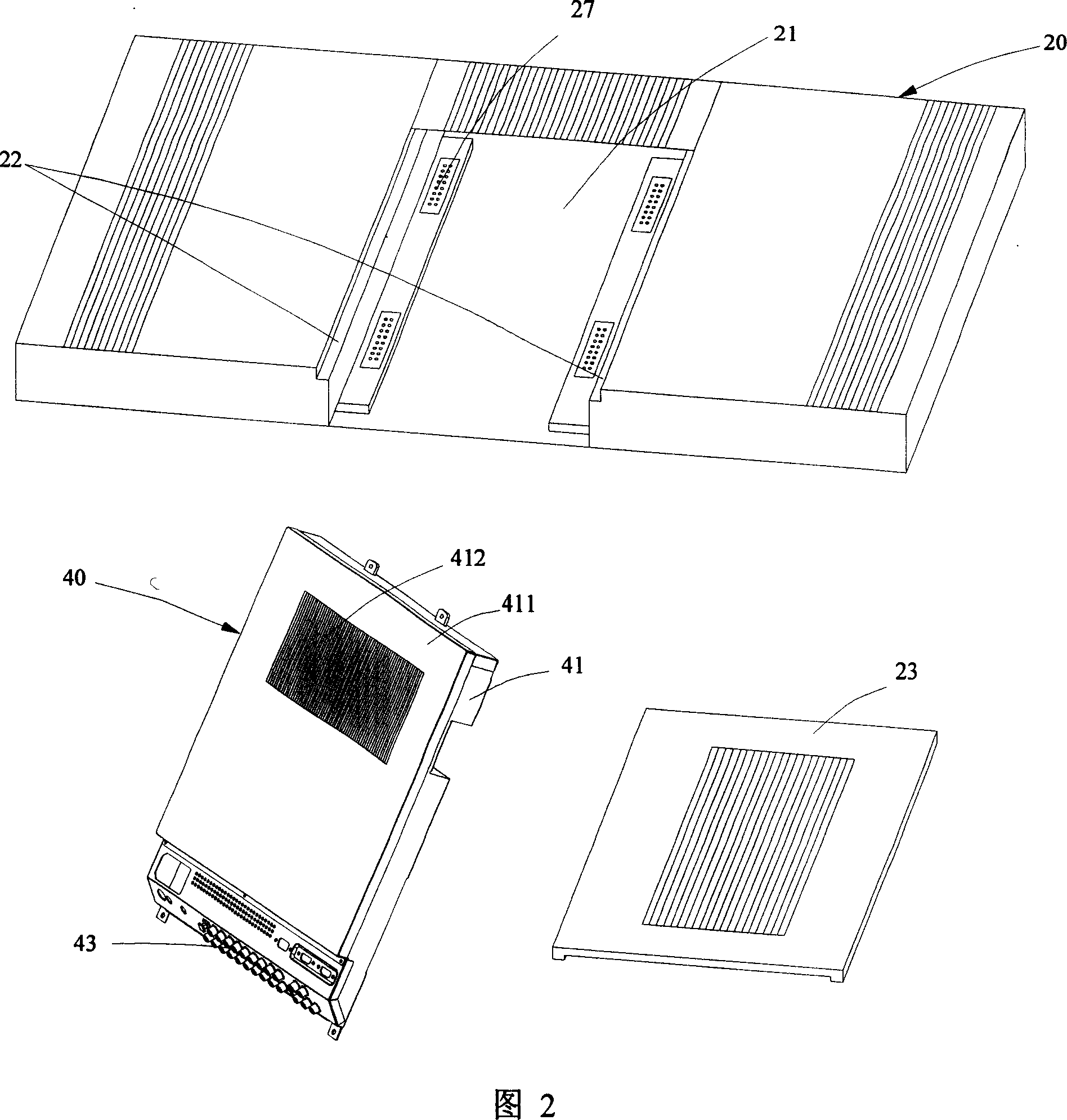
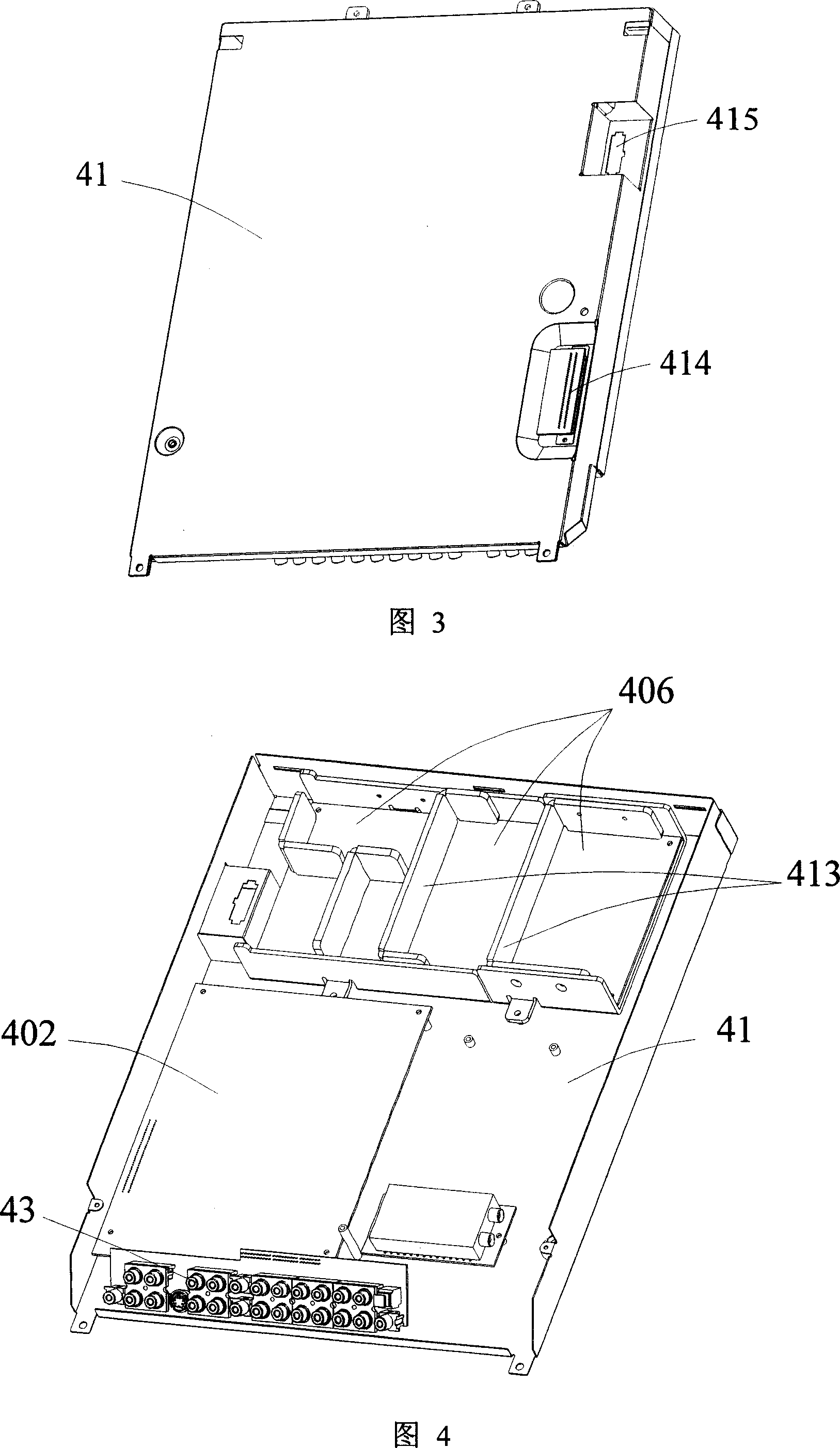
[0038] As shown in Figures 2 to 4, the utility model modular flat panel display device, especially a flat panel liquid crystal display TV, includes a housing 20, a display screen (not shown), a group of functional module components 40, a box body 41 and a Set of external terminals 43. The display screen is installed on one side of the housing 20; the box is installed on the other side of the housing 20; the functional module assembly 40 is installed in the box 41; the external terminal 43 is set On one side of the box body 41 .

[0039] The box body 41 is a metal shielding box, the inside of the lower frame is separated by a shielding plate 413 with a plurality of shielding areas, and one side of the box is installed as an upper cover 411 by screws or buckles, and the upper cover 411 is provided with The heat dissipation window grid 412, the side of the box body 41 is provided with a signal interface 414 and a power interface 415, the signal interface 414 is a D-SUB connector...


PUM


Abstract

The invention relates to a modularized flat display unit, comprising casing, display screen, display screen-drive functional module and external terminals, where the functional module is arranged in a box, and the box is removably installed on one side of the casing, and the external terminals are arranged on one side of the box. Thus, it reduces the design cost, and makes maintenance convenient. Besides, the external terminals are inclinedly arranged on the box to be able to effectively reduce parts of the wire projecting from the box so as to reduce the required installation space for the flat display unit; the flat display unit further adopts ''T''-shaped support device to effectively use vertical and cross bars to support the whole display unit, solving the problem that the support strength is not enough.

Description

technical field [0001] The present invention relates to a display device, more specifically, to a flat panel display device. Background technique [0002] A flat panel display device (such as a liquid crystal display, a liquid crystal TV, etc., and the liquid crystal display is used as an example below) is a display device designed by utilizing the principle that the alignment direction of liquid crystal molecules changes the polarization direction of incident light. Due to the superior performance of liquid crystal displays such as small space, thin panel thickness, light weight, flat right-angle display, low power consumption, no electromagnetic radiation, and no heat radiation, liquid crystal displays gradually replace CRT (Cathode Ray Tube) displays. Moreover, the technology of liquid crystal display is also developing rapidly. [0003] With more and more functions of the liquid crystal display, more and more functional modules are installed inside the liquid crystal di...

Claims


Application Information

Patent Timeline
Patent Type & Authority Applications(China)
IPC IPC(8): G02F1/133G09G3/00H04N5/44H04N21/41
Inventor 杨荣山黄明山张家瑶李胜为
Owner PROVIEW TECH SHENZHEN
Learn More