Multi-level efficient inverter

A multi-level inverter technology, applied to electrical components, AC power input conversion to DC power output, output power conversion devices, etc., can solve the problem of reducing inverter power supply efficiency, reducing the utilization rate of output inductance, and controlling Problems such as inconsistency of circuit parameters can achieve the effect of improving electromagnetic interference, reducing DC electromagnetic interference, and improving performance

Inactive Publication Date: 2015-02-18
SUZHOU LUAN NEW ENERGY TECH CO LTD
View PDF5 Cites 9 Cited by
  • Summary
  • Abstract
  • Description
  • Claims
  • Application Information

AI Technical Summary

Problems solved by technology

Bipolar SPWM modulates the complementary drive of two switch tubes of the same bridge arm. Due to the inconsistency of the switch tube conduction and cut-off characteristics and the inconsistency of the control circuit parameters of the dead time, the two switch tubes of the same bridge arm may be turned on at the same time. through, which will lead to damage to the switch tube
Unipolar SPWM control has: only one switch tube is used for high-frequency switching in the negative half cycle of the mains, resulting in a decrease in the utilization rate of the output inductor, thereby reducing the efficiency of the inverter power supply

Method used


Image

  • Multi-level efficient inverter
  • Multi-level efficient inverter
  • Multi-level efficient inverter

Examples


Embodiment Construction

[0025] In order to further illustrate the technical means adopted by the present invention and its effects, the following describes in detail in conjunction with preferred embodiments of the present invention and accompanying drawings.

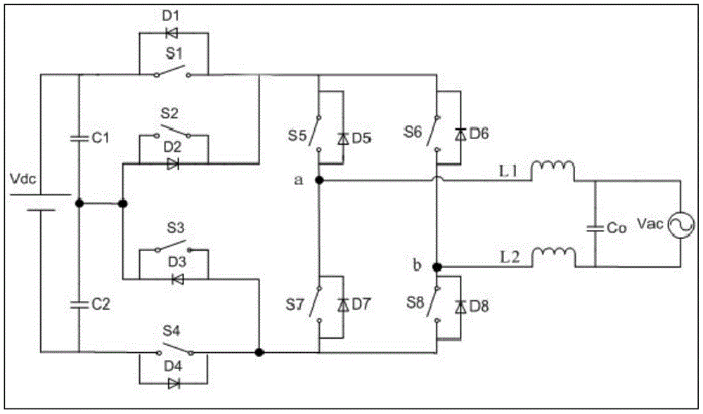
[0026] As shown in Figure 1, the current input terminal of the first switching tube S1 is connected to the positive pole of the DC power supply (Vdc), the positive pole of the first bus capacitor C1, and the cathode of the first diode D1 at the same time; the current of the first switching tube S1 The output terminal is simultaneously connected with the input of the second switching tube S2, the anode of the first diode D1, the cathode of the second diode D2, the input terminal of the fifth switching tube S5, the input terminal of the sixth switching tube S6, the fifth The cathode of the diode D5 is connected to the cathode of the sixth diode D6; the output terminal of the second switching tube S2 is simultaneously connected with the input term...


PUM


Abstract

The invention provides a multi-level efficient inverter and belongs to the technical field of inverters. The multi-level efficient inverter comprises a direct current power supply Vdc, an alternating current power supply Vac, a first switch tube S1, a second switch tube S2, a third switch tube S3, a fourth switch tube S4, a fifth switch tube S5, a sixth switch tube S6, a seventh switch tube S7, an eighth switch tube S8, a first diode D1, a second diode D2, a third diode D3, a fourth diode D4, a fifth diode D5, a sixth diode D6, a seventh diode D7, an eighth diode D8, a first filter inductor L1, a second filter inductor L2, a first bus capacitor C1, a second bus capacitor C1, a power frequency filter capacitor C0 and a microcontroller MCU. According to the multi-level efficient inverter, the efficiency of the inverter is improved, and the direct current electromagnetic interference can be reduced.

Description

technical field [0001] The invention relates to an inverter power supply, in particular to a multi-level high-efficiency inverter. Background technique [0002] The inverter is a power conversion device, mainly to realize the energy conversion from DC power to AC power. Grid-connected inverters include photovoltaic grid-connected inverters, wind energy grid-connected inverters, fuel cell grid-connected inverters, etc. The grid-connected inverter can efficiently convert the energy generated by renewable energy into alternating current with the same frequency and phase as the mains, which can be connected to the mains. [0003] Divided according to its circuit form: half-bridge inverter power supply and full-bridge inverter power supply. Among them, there are two control modes of the full-bridge inverter power supply: unipolar SPWM modulation and bipolar SPWM modulation. Bipolar SPWM modulates the complementary drive of two switch tubes of the same bridge arm. Due to the in...

Claims


Application Information

Patent Timeline
Patent Type & Authority Applications(China)
IPC IPC(8): H02M7/483
CPCH02M7/483H02M1/14H02M1/44
Inventor 刘继胜游永亮
Owner SUZHOU LUAN NEW ENERGY TECH CO LTD
Why Eureka
Try Eureka