Electromagnetic shielding device

A technology of electromagnetic shielding and electronic components, applied in the direction of magnetic/electric field shielding, electrical components, printed circuit components, etc., can solve the problems of difficult disassembly, etc., and achieve the effect of solving difficult disassembly and low reusability

Inactive Publication Date: 2007-10-10
ASUSTEK COMPUTER INC
View PDF0 Cites 3 Cited by
  • Summary
  • Abstract
  • Description
  • Claims
  • Application Information

AI Technical Summary

Problems solved by technology

[0007] The purpose of the present invention is to provide an electromagnetic shielding device, which uses conductive rubber to replace the part of the metal cover, so as to solve the problem that the conventional cover made of metal material is not easy to disassemble during maintenance.

Method used


Image

  • Electromagnetic shielding device
  • Electromagnetic shielding device
  • Electromagnetic shielding device

Examples


Embodiment Construction

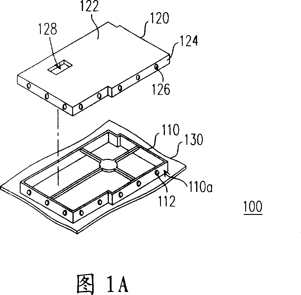
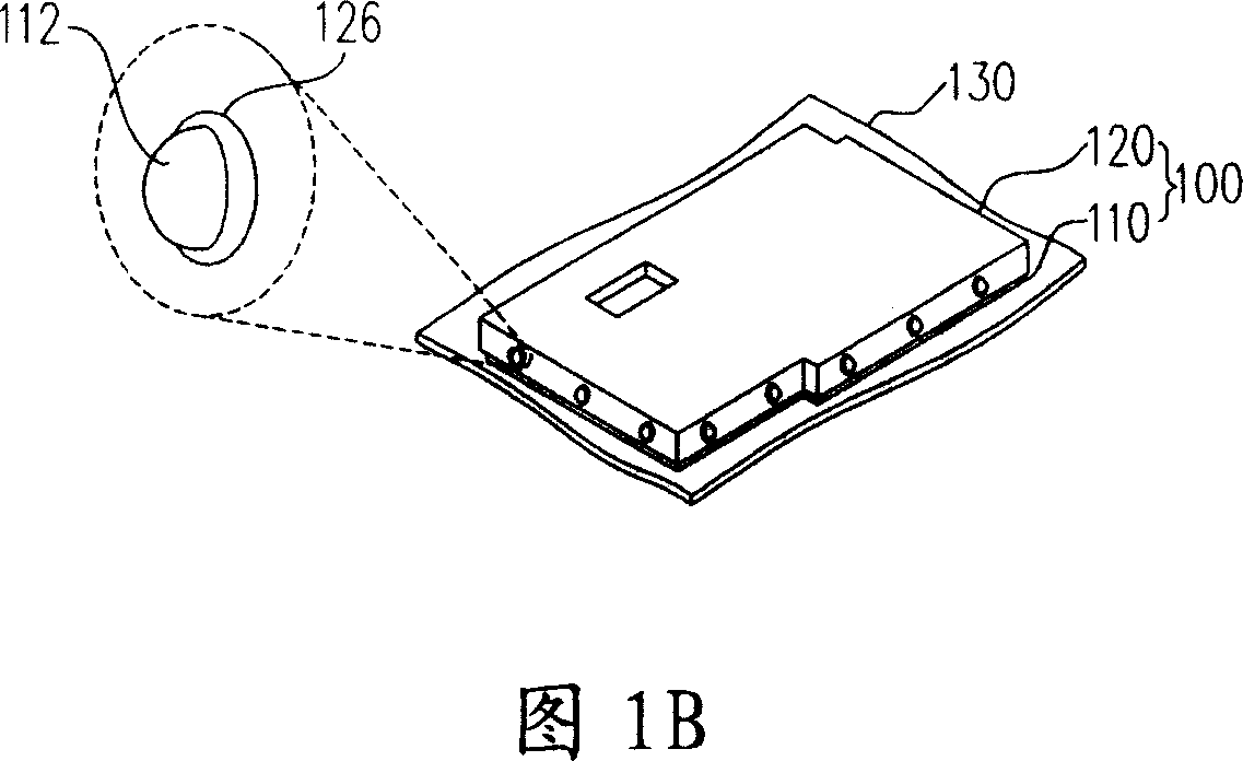
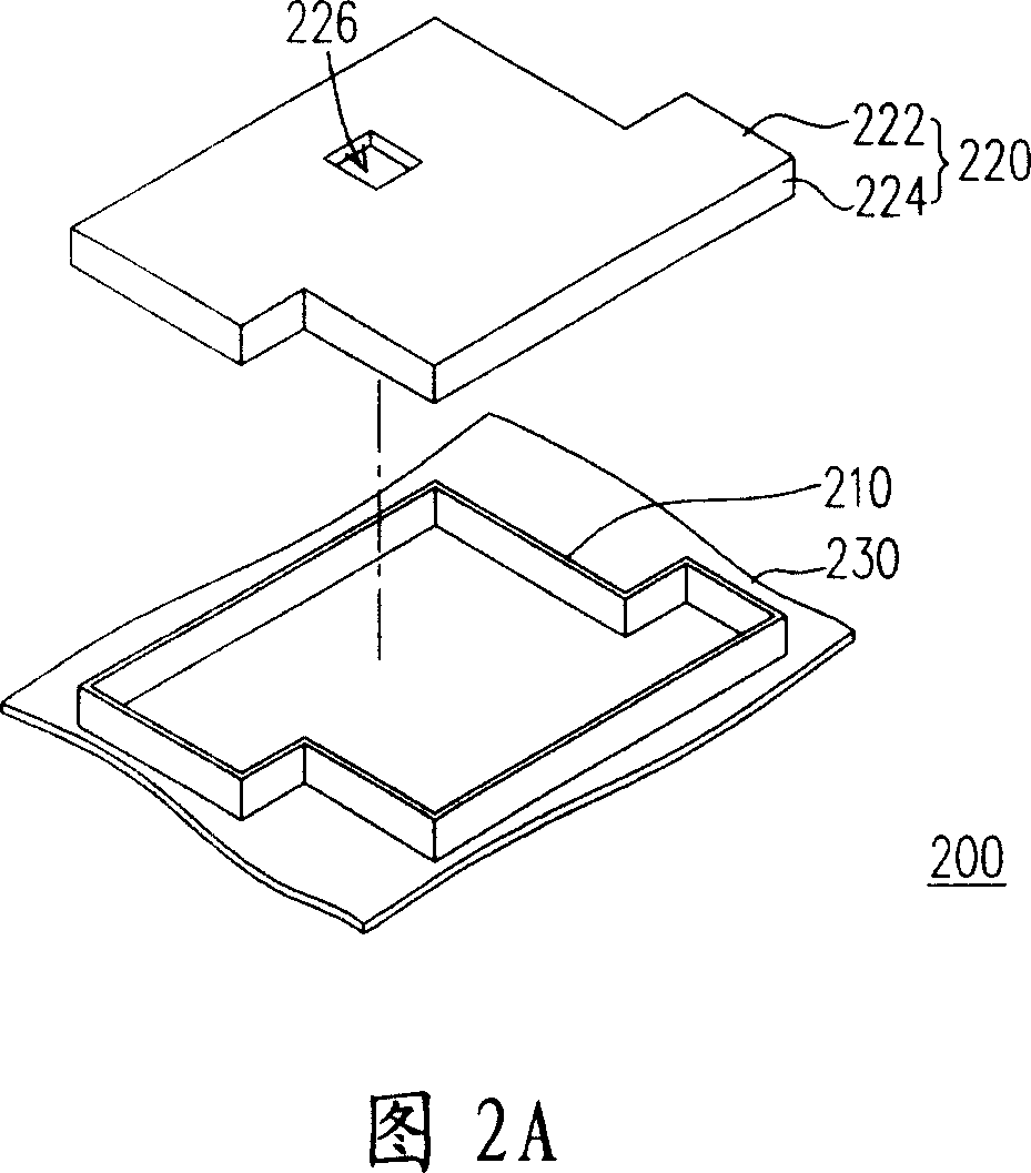
[0042] Please refer to FIG. 2A , which is an exploded perspective view of an electromagnetic shielding device according to an embodiment of the present invention; FIG. 2B is an assembled perspective view of the electromagnetic shielding device shown in FIG. 2A . Please refer to FIGS. 2A and 2B at the same time. The electromagnetic shielding device 200 is disposed on a printed circuit board 230 to surround an electronic component (not shown) disposed on the printed circuit board 230 . In this way, the interference caused by external electromagnetic waves to the electronic components on the printed circuit board 230 can be isolated by the electromagnetic shielding device 200 , and the leakage of electromagnetic waves can be prevented at the same time.

[0043] The electromagnetic shielding device 200 mainly includes a frame 210 and a cover 220 . The frame 210 can be fixed on the printed circuit board 230 by SMT process or other methods, and the frame 210 is made of metal materia...


PUM


Abstract

The invention is set up on a PCB. The electromagnetic shielding device comprises a frame and a cap. Said frame sits on the PCB and is made of metal material. Said cap is made of electroconductive rubber. The combination of the frame and the cap forms a sealed room to cover the electronic components on the PCB.

Description

technical field [0001] The present invention relates to an electromagnetic shielding device, and in particular to an electromagnetic shielding device using conductive rubber. Background technique [0002] Electromagnetic interference is one of the common problems in electronic equipment. Usually, the circuit will generate electromagnetic waves during application. This electromagnetic wave will affect the transmission signal and working performance of other electronic components. Since the mobile phone requires a faster signal transmission speed, it has a very high requirement for anti-electromagnetic interference. Generally speaking, an electromagnetic shielding device is disposed on a printed circuit board (PCB) of a mobile phone to prevent leakage of electromagnetic waves or interference caused by infiltration of external electromagnetic waves. [0003] Please refer to FIG. 1A , which is an exploded perspective view of a conventional electromagnetic shielding device; FIG....

Claims


Application Information

Patent Timeline
Patent Type & Authority Applications(China)
IPC IPC(8): H05K1/02H05K9/00
Inventor 陈铭滨
Owner ASUSTEK COMPUTER INC
Why Eureka
Try Eureka