Device for cleaning fiber wadding

A technology of cleaning equipment and fiber wadding, which is applied in the field of fiber wadding cleaning equipment, can solve the problems of reducing the cleaning efficiency of cleaning equipment, and achieve the effect of high throughput

Inactive Publication Date: 2007-10-10
MASCHINENFABRIK RIETER AG
View PDF7 Cites 7 Cited by
  • Summary
  • Abstract
  • Description
  • Claims
  • Application Information

AI Technical Summary

Problems solved by technology

In addition, fiber batt material thus enters the outlet stream without extensive cleaning, reducing the cleaning efficiency of the cleaning equipment
Another disadvantage is the formation of vortices by excess transport of air, especially by cross flow

Method used


Image

  • Device for cleaning fiber wadding
  • Device for cleaning fiber wadding
  • Device for cleaning fiber wadding

Examples


Embodiment Construction

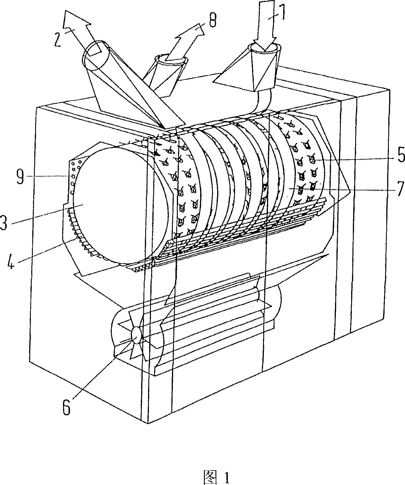
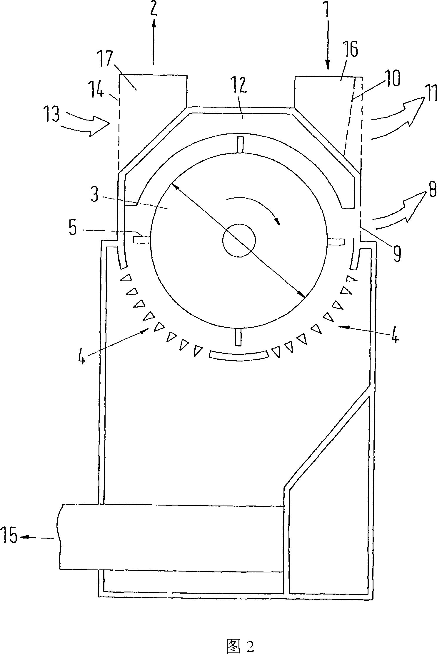
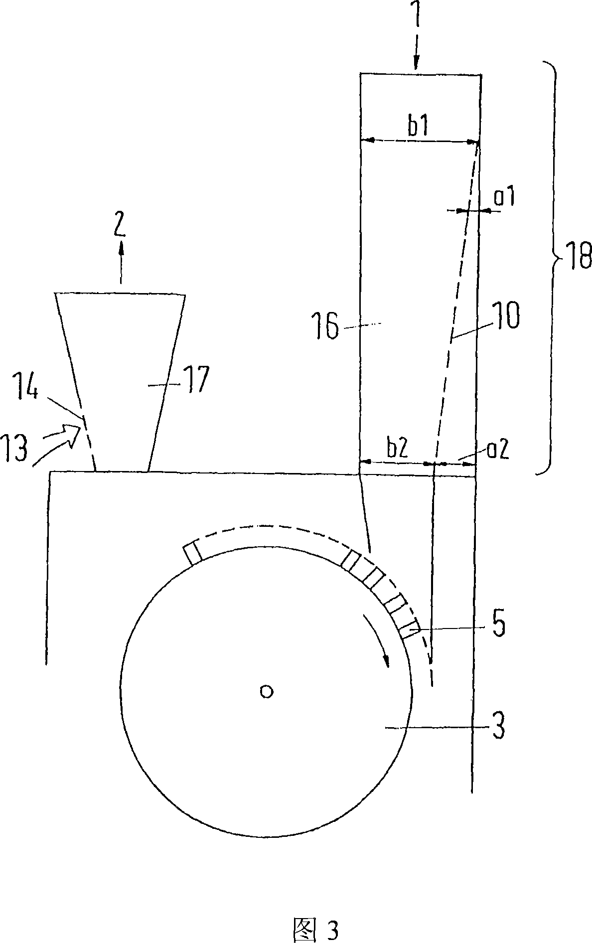
[0022] According to the prior art, a cleaning device is described with reference to FIG. 1 , see also documents EP381860, EP379726 and EP447966, which disclose similar devices in more detail and which form an integral part of the present application. The cleaning device shown in FIG. 1 includes an opening roller 3, which is installed in a housing and can rotate around a horizontal axis, and the circumference of the roller is usually equipped with a beating member 5, such as a beating pin or a tooth pin. During operation, the roller 3 rotates in the direction of the arrow through a drive motor (not shown). Below the underside of the roller 3 is provided with a cleaning grid 4 .

[0023] The upper side of the roller 3 is covered at a distance from the periphery of the roller by a wall which is provided with a horizontal middle area and two side areas which are laterally adjoining the horizontal middle area and are inclined at approximately 45°, and in addition are provided with ...


PUM


Abstract

The invention relates to a cleansing device for fibre flocks, in particular, of cotton, with a horizontal roller, fitted with impact elements, with an inlet on the upper side at one end of the roller and an outlet at the other end for the feed stream. Transfer chambers defined by guide plates are placed at an angle to the roller axis between the inlet opening and the outlet opening for the feed stream rotating about the roller axis. The fibre flock stream can be compacted by provision of an air separation device before the inlet opening, which gives the cleansing device an improved cleansing with increased production.

Description

technical field [0001] The invention relates to a cleaning device for fiber batts, in particular consisting of cotton, comprising a horizontal roller, which is equipped with a beating element, and on the upper side of the roller, at one end of the roller, a conveying flow inlet is provided, At the other end, however, a conveying flow outlet is provided, and between the inlet and the outlet there are transfer chambers delimited by guide plates inclined to the roller axis, which serve to rotate the conveying flow about the roller axis. Background technique [0002] At least one such cleaning device is known and commercially available. This device serves to open the fiber batt supplied in the conveying air stream and remove impurities therefrom. The fibrous material is supplied together with conveying air to the axial ends of the rollers via the inlet. The air-fiber floes are conveyed helically around the rollers so that they are guided multiple times over the cleaning grid. ...

Claims


Application Information

Patent Timeline
Patent Type & Authority Applications(China)
IPC IPC(8): D02G3/04
CPCD01G9/10D01G9/02
Inventor 瓦尔特・施勒普费尔西蒙・海尼格
Owner MASCHINENFABRIK RIETER AG
Why Eureka
Try Eureka