Novel straight seam welding machine

A new type of straight seam welding technology, applied in welding equipment, auxiliary welding equipment, welding/cutting auxiliary equipment, etc., can solve the problems of inconvenience, low processing efficiency, and very large workload, and achieve convenient use and improve work efficiency. The effect of efficiency

Inactive Publication Date: 2007-10-24
黄卓明
View PDF1 Cites 18 Cited by
  • Summary
  • Abstract
  • Description
  • Claims
  • Application Information

AI Technical Summary

Problems solved by technology

[0002] At present, there is a straight seam welding machine for welding metal plates, which includes left and right clamping beds arranged on the machine body. The positions of the left and right clamping beds are relatively fixed. The operator places the two metal plates to be welded on the In the left and right clamping beds, the two metal plates are clamped by the clamping bed and then welded. In order to accurately weld the two metal plates together, the operator needs to observe with the naked eye when placing the metal plates. Align the welding edges of the two plates; the operator can easily do this when the metal plates are thick and short, but when the metal plates to be welded are thin and long, the length exceeds When the clamping bed clamps the supporting area of ​​the table, due to the deformation of the plates during the placement process, it is difficult for the operator to align the two metal plates with the naked eye, and the upper and lower overlaps of the plates or between the seamed edges often occur. If the distance is uneven, the welded metal sheet does not meet the requirements. On the one hand, the material is wasted. On the other hand, the processing efficiency is low, which cannot meet the requirements of modern processing levels. It is necessary to improve
[0003] Usually, in order to make the clamp have sufficient rigidity and strength and ensure that the clamp is not deformed during use, multiple clamps are usually installed in parallel on the connecting plate on the clamp bed and connected side by side to form a clamp group. The unique vertical and horizontal adjustment mechanism is connected with the connecting plate flexibly. Since the thickness of the metal sheets to be welded is different, the position of each fixture must be adjusted each time to better clamp the workpiece. When the length of the clamping bed reaches 2-3m Even longer, there are nearly a hundred clamps on it, so if you want to adjust each clamp to a suitable position, the adjustment workload will be very large, which is not convenient for the operator to use, and further improvement is necessary

Method used


Image

  • Novel straight seam welding machine
  • Novel straight seam welding machine
  • Novel straight seam welding machine

Examples


Embodiment Construction

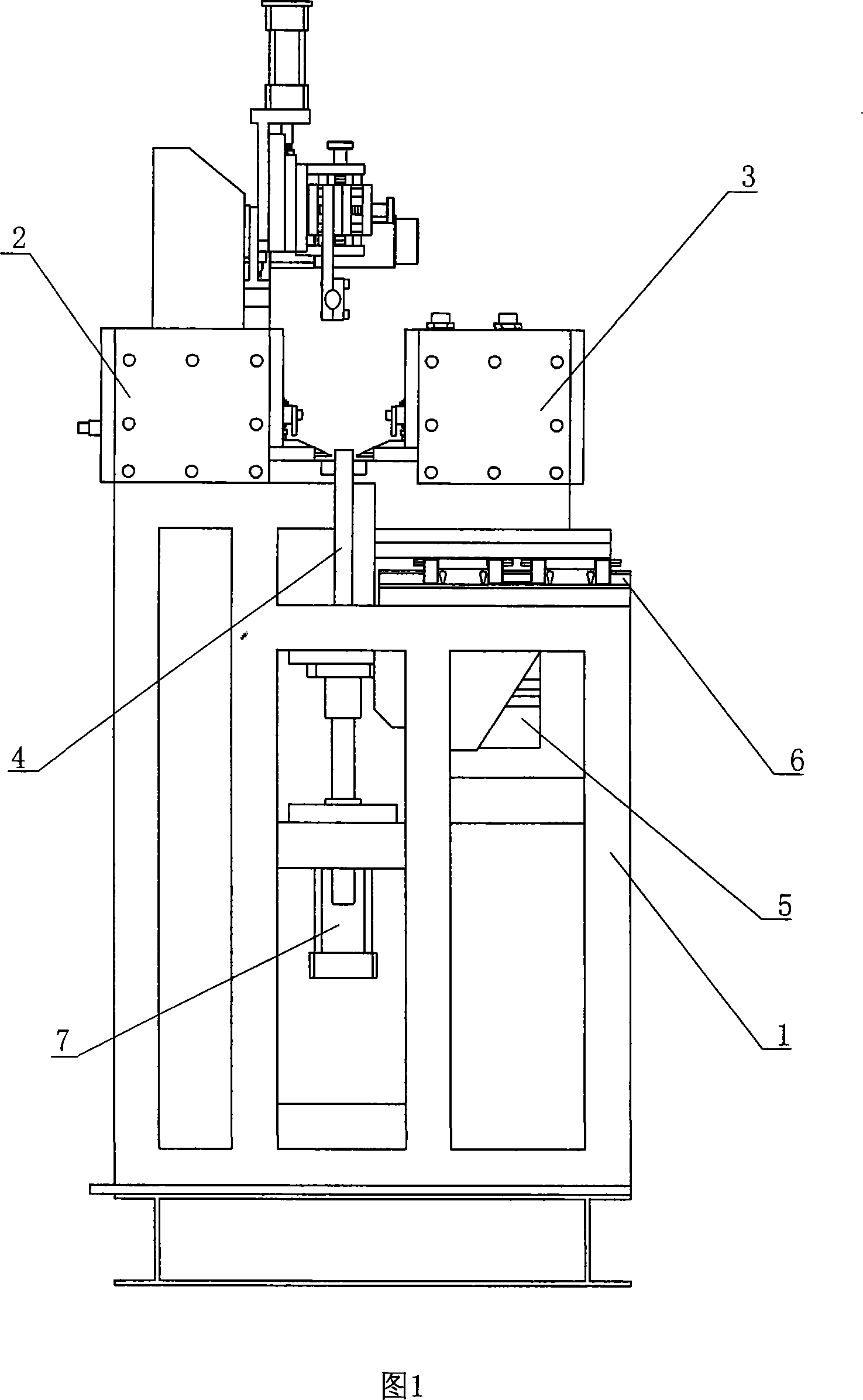
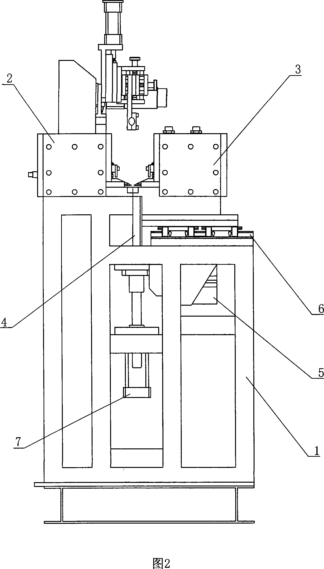
[0021] Referring to Fig. 1 and Fig. 2, a new type of straight seam welding machine includes a body 1, which is provided with left and right clamping beds 2, 3, and the horizontal direction of the clamping table tops of the left and right clamping beds 2, 3 is Alignment, the bottom of the right clamping bed 3 is provided with a slide rail 6, and a driving device 5 drives the right clamping bed 3 to translate along the slide rail 6 in the left and right direction of the body 1, and the body 1 is provided with a limiting plate 4, which limits The position plate 4 links to each other with the driving device two 7, drives the position limiting plate 4 to expand and contract between the left and right clamping beds 2,3 by the driving device two 7.

[0022] The working principle of the present invention is: when metal plate is welded and stitched, first utilize the driving device 2 7 to drive the limiting plate 4, so that the limiting plate 4 is lifted out and placed between the left ...


PUM


Abstract

The invention relates to a new direct seam soldering machine that comprises the machine with left and right clamping bed whose horizontal direction being in alignment, the bottom of the said right clamp bed, the drive mechanism driving the right clamp bed sliding along the track, the said lathe having restraint plate that connected with the drive mechanism, through which the two driven restraint plate extending between the right and left clamp beds. It is reasonable in structure, easily aligning the two blocks of metal and welding them together, with high working efficiency, with the metal conforming to the standard. It is a direct welding machine for the welding of metals.

Description

technical field [0001] The invention relates to a welding jigsaw device, in particular to a novel straight seam welding machine for welding metal plates. Background technique [0002] At present, there is a straight seam welding machine for welding metal plates, which includes left and right clamping beds arranged on the machine body. The positions of the left and right clamping beds are relatively fixed. The operator places the two metal plates to be welded on the In the left and right clamping beds, the two metal plates are clamped by the clamping bed and then welded. In order to accurately weld the two metal plates together, the operator needs to observe with the naked eye when placing the metal plates. Align the welding edges of the two plates; the operator can easily do this when the metal plates are thick and short, but when the metal plates to be welded are thin and long, the length exceeds When the clamping bed clamps the supporting area of ​​the table, due to the d...

Claims


Application Information

Patent Timeline
Patent Type & Authority Applications(China)
IPC IPC(8): B23K37/04
Inventor 黄卓明
Owner 黄卓明
Why Eureka
Try Eureka