Cylindrical structure anisotropy testing device based on ultrasonic waves

An anisotropy, testing device technology, applied in measurement devices, analysis of solids using sonic/ultrasonic/infrasonic waves, material analysis using sonic/ultrasonic/infrasonic waves, etc. It is difficult to maintain the centering of the transmitting probe and the receiving probe, increasing the complexity of theoretical analysis, etc., so as to improve the test efficiency, save the test time, and save the installation time.

Pending Publication Date: 2020-08-07
CHINA UNIV OF PETROLEUM (EAST CHINA)
View PDF5 Cites 0 Cited by
  • Summary
  • Abstract
  • Description
  • Claims
  • Application Information

AI Technical Summary

Problems solved by technology

Since the elastic constants of anisotropic materials vary with direction, it also increases the complexity of theoretical analysis
The anisotropy test of block structure or block sample is relatively simple and can be realized by uniaxial compression experiment, and if figure 1 Since the cylindrical structure sample shown is a curved surface, the anisotropy in the radial direction (direction 1) and axial direction (direction 2) cannot be measured by the traditional uniaxial compression test.
Ultrasonic testing is widely used in material performance testing, but the cylindrical structure is a curved surface, the installation of the ultrasonic probe requires an additional curved surface device, and it is difficult to maintain the alignment of the transmitting probe and the receiving probe, which affects the test results

Method used


Image

  • Cylindrical structure anisotropy testing device based on ultrasonic waves
  • Cylindrical structure anisotropy testing device based on ultrasonic waves
  • Cylindrical structure anisotropy testing device based on ultrasonic waves

Examples


Embodiment Construction

[0013] In order to make the object, technical solution and advantages of the present invention clearer, the present invention will be described in detail below through specific examples.

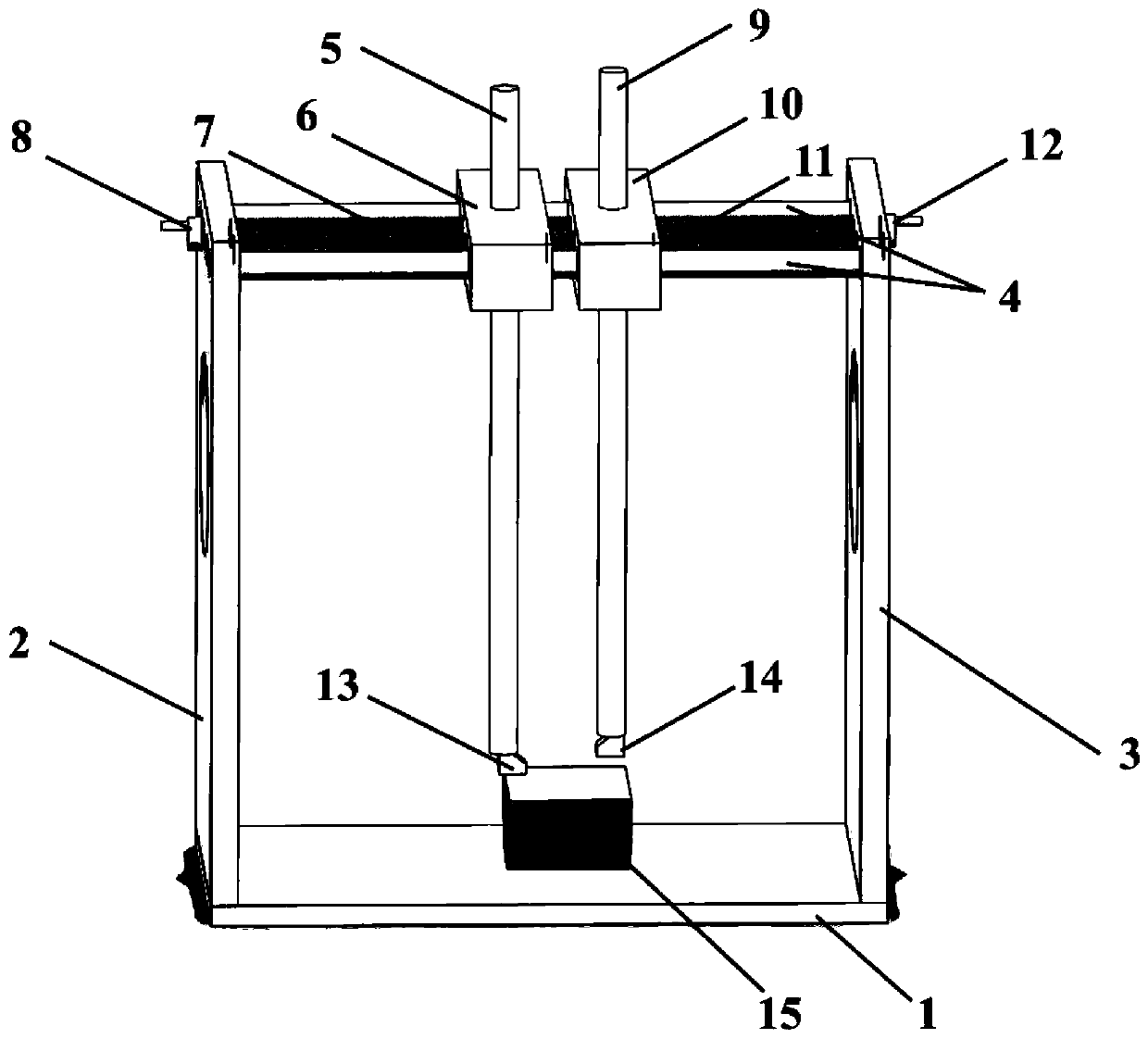
[0014] see figure 2 , the present invention provides a cylindrical structure anisotropy testing device based on ultrasonic waves, comprising: a bottom plate 1, a left side plate 2 and a right side plate 3 symmetrically arranged on both sides of the bottom plate 1, and a left side plate 2 and a right side plate arranged in parallel Two smooth round rods 4 between the plates 3 and the first screw 7 and the second screw 11, the left slider 6, the right slider 10, the ultrasonic transmitting probe 13, the ultrasonic receiving probe 14, the first screw 7, the second Two screw rods 11 are located between two smooth round rods 4, and the two ends of the first screw rod 7 and the second screw rod 11 are respectively arranged on the left side plate 2 and the right side plate 3 through bearings, and ...


PUM


Abstract

The invention discloses a cylindrical structure anisotropy testing device based on ultrasonic waves. The device comprises a bottom plate, a left side plate and a right side plate which are arranged atthe two sides of the bottom plate, two smooth round rods, a first screw and a second screw which are arranged between the left side plate and the right side plate, a left sliding block, a right sliding block, an ultrasonic transmitting probe and an ultrasonic receiving probe, wherein one end of the first screw rod penetrates through the left side plate and then is connected with a left rocking wheel, and one end of the second screw rod penetrates through the right side plate and then is connected with a right rocking wheel; the left sliding block and the right sliding block sequentially sleeve the two smooth round rods. the left sliding block penetrates through the second screw rod and then is in threaded connection with the first screw rod, and the right sliding block penetrates throughthe first screw rod and then is in threaded connection with the second screw rod; a first round rod is vertically arranged on the left sliding block, and the first round rod is connected with the ultrasonic transmitting probe; a second round rod is vertically arranged on the right sliding block, and the second round rod is connected with the ultrasonic receiving probe. The testing device solves the problem that the anisotropy of the curved surfaces, such as the cylindrical structures, etc., cannot be rapidly and accurately tested in the prior art.

Description

【Technical field】 [0001] The invention relates to the fields of ultrasonic testing and experimental mechanics, in particular to an ultrasonic-based cylindrical structure anisotropy testing device. 【Background technique】 [0002] Cylindrical structures or round rods are widely used in engineering, such as bridge piers in civil engineering, sucker rods in petroleum engineering, etc. Anisotropy means that all or part of the chemical and physical properties of materials change with the change of direction, showing different properties in different directions. Since the elastic constants of anisotropic materials vary with direction, it also increases the complexity of theoretical analysis. The anisotropy test of block structure or block sample is relatively simple and can be realized by uniaxial compression experiment, and if figure 1 Since the cylindrical structure sample shown is a curved surface, the anisotropy in the radial direction (direction 1) and axial direction (direc...

Claims


Application Information

Patent Timeline
IPC IPC(8): G01N29/07G01N29/22
CPCG01N29/07G01N29/223G01N2291/011G01N2291/02827G01N2291/102
Inventor 张毅贾朋薛世峰叶贵根孙峰朱秀星
Owner CHINA UNIV OF PETROLEUM (EAST CHINA)
Why Eureka
Try Eureka