Supercharge Your Innovation With Domain-Expert AI Agents!

Multi-direction round clamping device

A clamping device and circular rotation technology, applied in the field of machining, can solve the problem of not being able to carry out multiple machining processes at the same time, and achieve the effects of improving machining efficiency, beautiful appearance and convenient maintenance.

Inactive Publication Date: 2007-10-24
刘继东 +1
View PDF0 Cites 15 Cited by
  • Summary
  • Abstract
  • Description
  • Claims
  • Application Information

AI Technical Summary

Problems solved by technology

[0005] The embodiment of the present invention aims to provide a multi-directional circular clamping device, which can solve the problem that multiple machining processes cannot be performed simultaneously in the prior art

Method used


Image

  • Multi-direction round clamping device
  • Multi-direction round clamping device

Examples


Embodiment Construction

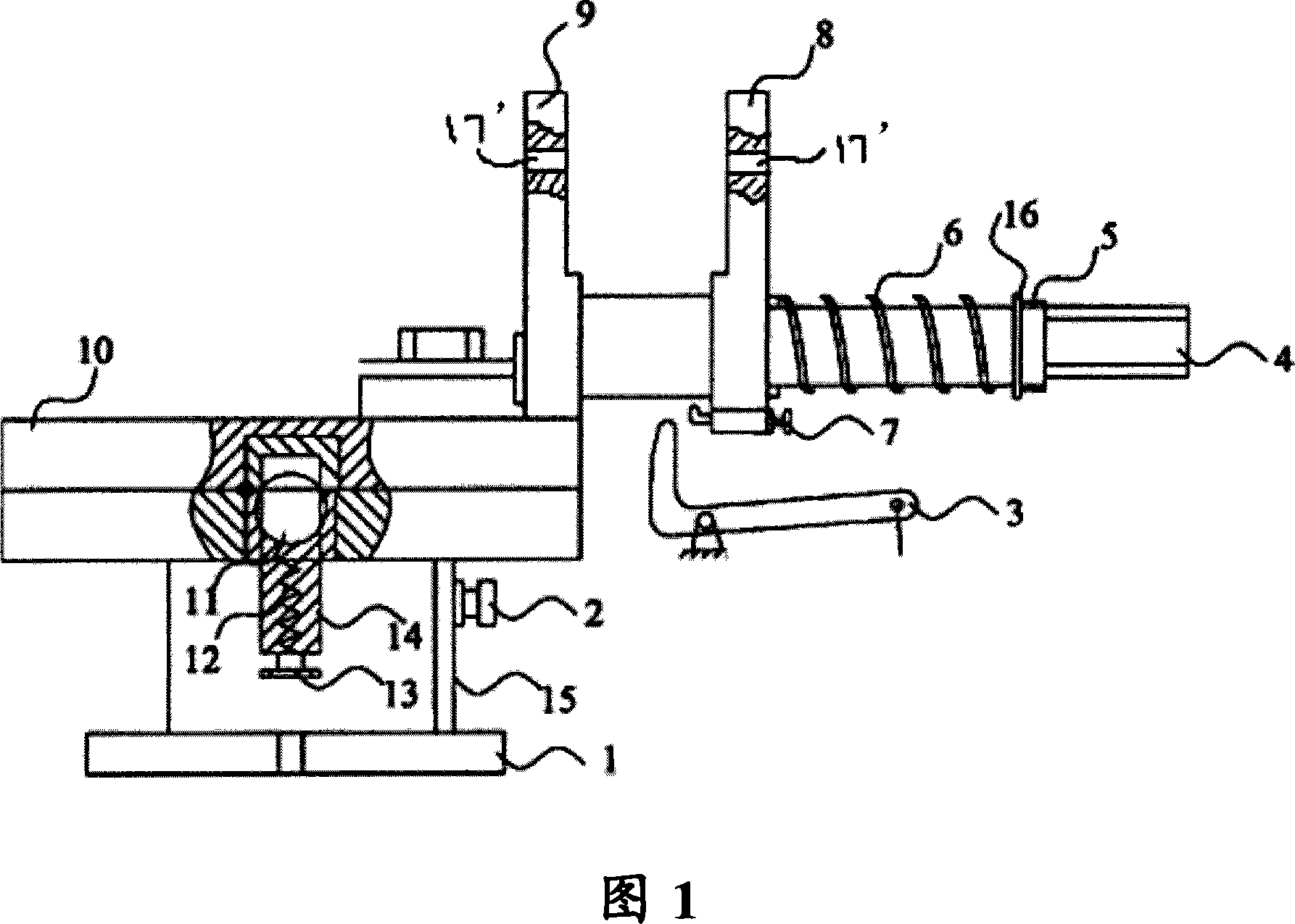
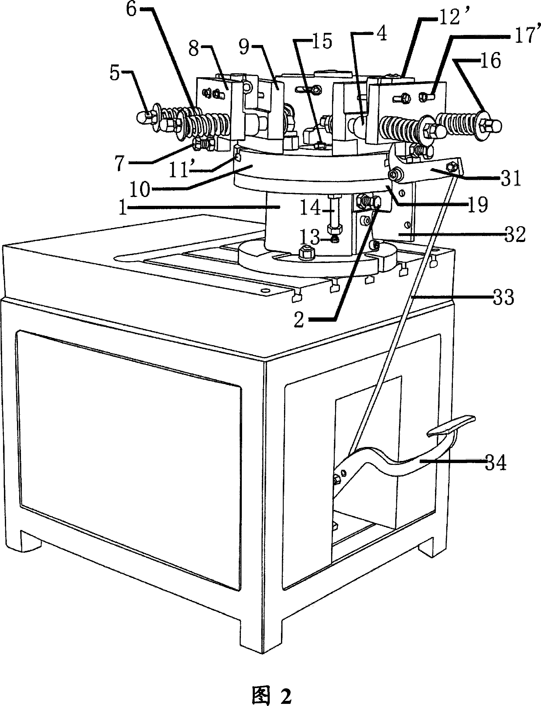
[0020] The present invention will be described in detail below with reference to the accompanying drawings and in combination with embodiments. For the convenience of illustration, the following drawings and descriptions use three vises as examples to illustrate multiple clamping tools, so as to illustrate the multi-directional circular clamping device according to the embodiment of the present invention.

[0021] Fig. 1 shows a schematic diagram of one direction of a three-way vise circular turning device according to an embodiment of the present invention. The three-way vise circular turning device includes: three vises and a circular turntable, one of which is shown in the figure vise.

[0022] The circular turntable mainly includes: a transposition turntable 10, a base plate 1 and a central axis 15, wherein the transposition turntable 10 is connected to the base plate 1 through the central axis 15, and can rotate around the central axis 15, and its upper surface includes t...


PUM


Abstract

The invention provides a multi directional round clamping device that comprises the rotor that comprises the shift rotor, bottom plate and the central shaft, with the rotor connected to the bottom plate through the middle shaft, rotating around the middle shaft with its top surface composed of n equally separated fixed slot along the circumference, to of the middle shaft composed of outer extended round plate, whose top surface formed into face contact with the bottom surface of the shift rotor and supporting the shift rotor, N clamping tools fixed to the each fixing slot.

Description

technical field [0001] The invention relates to the field of mechanical processing, more specifically, to a multi-directional circular clamping device, in particular to a three-directional vise circular rotary device. Background technique [0002] The vise is mainly used in the field of mechanical processing such as drilling, milling and tapping. Its function is reflected in that it can be used to clamp the workpiece, so that the drilling, milling or tapping head can drill, mill and tap the workpiece. [0003] In the course of realizing the present invention, the inventor finds that there are at least the following problems in the prior art: [0004] When the existing clamping device performs multiple processes such as drilling, milling, and tapping on the workpiece, it must be performed sequentially and cannot be performed simultaneously, thus resulting in low machining efficiency. Contents of the invention [0005] The embodiment of the present invention aims to provide...

Claims


Application Information

Patent Timeline
IPC IPC(8): B23Q3/06B23Q3/08B23Q1/25
Inventor 刘继东张金宝
Owner 刘继东
Features
  • R&D
  • Intellectual Property
  • Life Sciences
  • Materials
  • Tech Scout
  • Unparalleled Data Quality
  • Higher Quality Content
  • 60% Fewer Hallucinations
Learn More