
Yarn end cutting method for spinning machine

A technology of spinning machine and yarn tail, which is applied in the field of yarn tail cutting of spinning machine, and can solve problems such as inability to hold yarn

Inactive Publication Date: 2010-06-02
TOYOTA IND CORP
View PDF6 Cites 0 Cited by
  • Summary
  • Abstract
  • Description
  • Claims
  • Application Information

AI Technical Summary

Problems solved by technology

Therefore, when the yarn tail cutting member 52 after leaving the bobbin 55 comes into contact with the spindle base 53a, the yarn Y cannot be grasped (clamped) by the yarn tail cutting member 52 and the spindle base 53a easily.

Method used


Image

  • Yarn end cutting method for spinning machine
  • Yarn end cutting method for spinning machine
  • Yarn end cutting method for spinning machine

Examples


Embodiment Construction

[0020] Below, according to Figure 1A to Figure 5B One embodiment of the present invention will be described. One embodiment shows a method for cutting a yarn tail of a ring spinning frame.

[0021] image 3 A spindle drive system for rotating a plurality of spindles 11 is shown. The spindle drive system includes: a spindle motor 12, a drive pulley 13 driven by the spindle motor 12, a driven pulley 14, and a tangential transmission belt (dragon belt) wound around the drive pulley 13 and the driven pulley 14. 15. A tangential drive belt 15 is wound on a plurality of spindles 11 .

[0022] image 3 A lift motor 23 for lifting and lowering the ring bar 17 is shown. A servo motor is used as the lift motor 23 . The traveler T moves along the ring 17 a provided in the ring shoe 17 . The main shaft 16 is connected to the drive shaft of the elevating motor 23 via a gear mechanism (not shown). The main shaft 16 extends along the arrangement of the plurality of spindles 11 . O...


PUM


Abstract

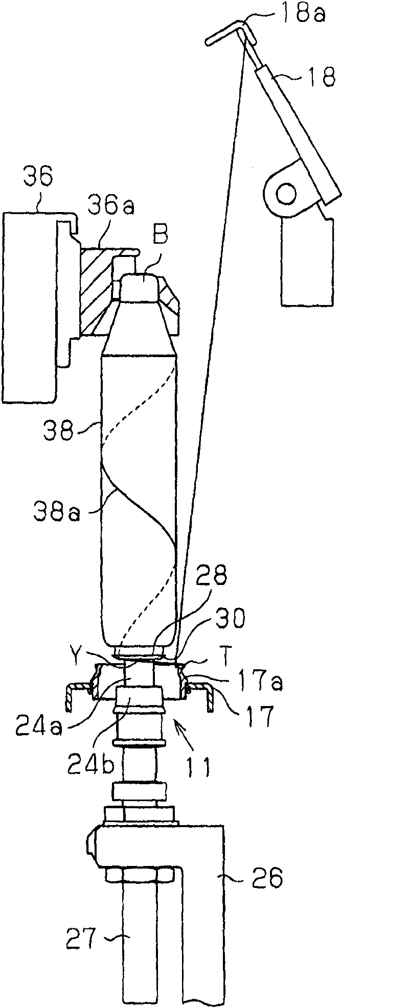
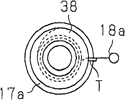
When doffing stops, to make the ring bar (17) be at the position corresponding to the pontes which connects with the yarn tail cutting part (28) relative to the hasp base (24b). Under the state that the cop (38) connecting to the yarn (Y) of the steel wire ring (T) wind until the position under the pontes, to stop the hasp (11). Under the state of stopping the hasp, to pull up the cop (38) from the hasp through the doffing device. During the midway of pulling up the cop (38), to make the yarn tail cutting part (28) ascend with the cop. When pulling up the cop (38) from the hasp through the doffing device, to make the ring bar ascend. To hold the mentioned yarn (Y) between the yarn tail cutting part (28) which has been divorced from the cop (38) and the hasp base (24b). To cut off the mentioned yarn (Y) by means of cutting part (30). Thus, to reduce the residual yarn tail on the hasp base and the yarn leakage cutting (pig 1B).

Description

technical field [0001] The invention relates to a yarn tail cutting method of a spinning machine. Specifically, the above-mentioned spinning machine includes a ring spinning frame or a ring twisting machine capable of raising and lowering a yarn end cutting member along a spindle bar extending above the spindle base. The yarn tail cutting member includes a bobbin insertion portion and a cutting portion located below the bobbin insertion portion. The end cutting part and the spindle base are able to hold (clamp) the yarn from the bobbin to the traveler. Background technique [0002] Spinning machines such as ring spinning frames or ring twisting machines require automatic tube changes when they are full. In other words, the spinning machine is required to automatically perform an operation of replacing a bobbin that has been wound with a yarn with an empty bobbin. Specifically, the spinning machine requires that the yarn be automatically wound onto an empty bobbin when it ...

Claims


Application Information

Patent Timeline
Patent Type & Authority Patents(China)
IPC IPC(8): D01H9/16D01H1/38
Inventor 药司诚天野久男
Owner TOYOTA IND CORP
Learn More