Supercharge Your Innovation With Domain-Expert AI Agents!

HV starting circuit for AC-DC converter

A high-voltage start-up and converter technology, which is applied to output power conversion devices, conversion equipment with intermediate conversion to AC, instruments, etc., can solve the problems of prolonged start-up response time, etc., to overcome power loss, improve efficiency, and system stability Effect

Inactive Publication Date: 2007-10-24
SUPEC SUZHOU
View PDF0 Cites 6 Cited by
  • Summary
  • Abstract
  • Description
  • Claims
  • Application Information

AI Technical Summary

Benefits of technology

This technology helps improve the performance of an electronic device's voltage regulator (VR) when it starts up again at very early stages during operation without losing its ability to adjust output levels accurately or efficiently. It also eliminates any leaks caused by previous designs while still providing efficient energy usage for all parts within the VR. Overall this makes the overall functioning more reliable and effective over time.

Problems solved by technology

This patented describes how conventional circuits work well when they start up with high voltages at certain points within them (the punching point). However, if there are changes or variations during this process, these modifications can lead to electrical disconnection from other parts of the device due to excessive currents flowing into their components over long periods of use without being detected by existing technology methods like sensors.

Method used


Image

  • HV starting circuit for AC-DC converter
  • HV starting circuit for AC-DC converter
  • HV starting circuit for AC-DC converter

Examples


Embodiment Construction

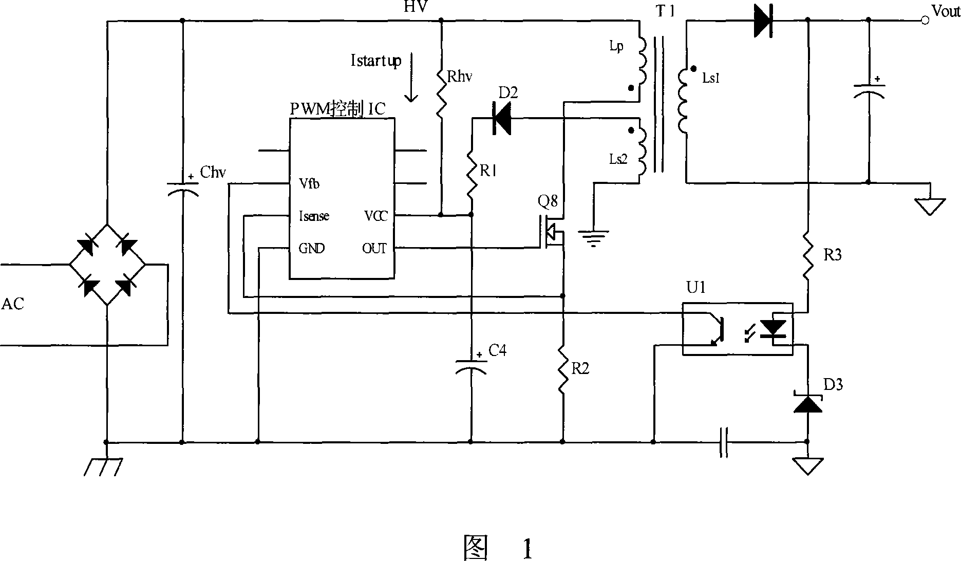
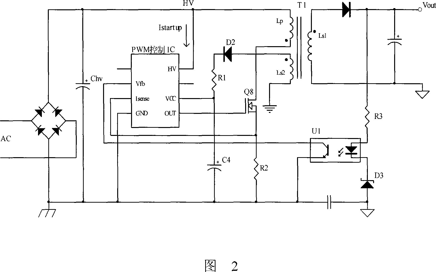
[0048]Referring to FIG. 2 , it is a high-voltage starting circuit diagram of an AC-DC converter according to a specific embodiment of the present invention. As shown in the figure, the high-voltage AC is rectified by the rectifier bridge to convert the sinusoidal signal into a pulsating DC signal, and then filtered by the filter capacitor Chv to obtain a smoother high-voltage DC signal, which provides the starting high-voltage HV. The high-voltage AC input range is between 64V and 264V, and the obtained DC high voltage range is between 30V and 500V. The starting high voltage HV is directly connected to the pin HV of the PWM control IC through a wire to provide the starting current Istartup. Through the PWM control IC internal circuit opening and closing action, the system completes the startup, and automatically closes the leakage path from the startup high voltage HV to the ground, and the startup current Istartup becomes 0. The pin VCC of the PWM control IC is grounded thro...


PUM


Abstract

The high-voltage startup circuit for AC-DC converter comprises: a PWM control IC including a TFT and a startup/close circuit, and a power supply circuit, wherein one pin of the PWM controlled IC connects with the startup high-voltage through wire. This invention develops current technique, reduces energy loss and cost, improves system performance, and then has well technical and economic benefits.

Description


Claims


Application Information

Patent Timeline
Owner SUPEC SUZHOU
Features
  • R&D
  • Intellectual Property
  • Life Sciences
  • Materials
  • Tech Scout
  • Unparalleled Data Quality
  • Higher Quality Content
  • 60% Fewer Hallucinations
Learn More