Monitoring system, monitoring method, and camera terminal

A monitoring system and camera technology, which is applied in the field of monitoring systems, can solve the problems of unconsidered camera operation, complicated preset operation, and inability to preset, etc.

Active Publication Date: 2007-10-24
PANASONIC CORP
View PDF3 Cites 14 Cited by
  • Summary
  • Abstract
  • Description
  • Claims
  • Application Information

AI Technical Summary

Problems solved by technology

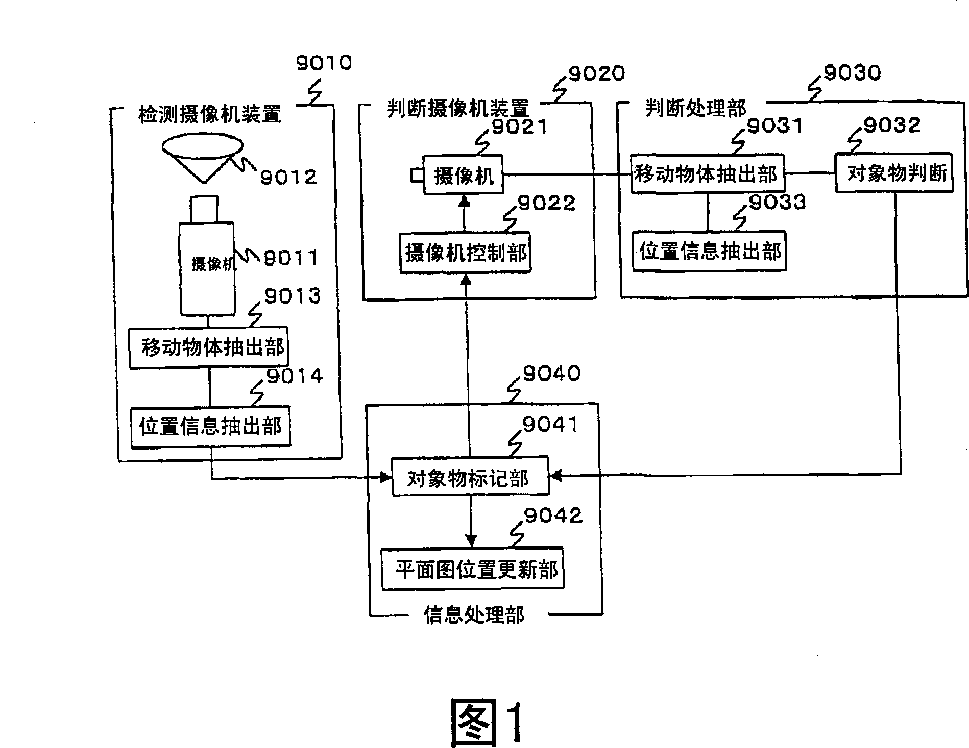
[0015] More specifically, in the moving object detection and determination device of Patent Document 1, in order to eliminate blind spots, the imaging area of ​​the detection camera device is fixed, so when the number of moving objects increases and it is determined that the camera device cannot capture images with a predetermined resolution, the detection The camera device cannot flexibly respond to high-resolution photography
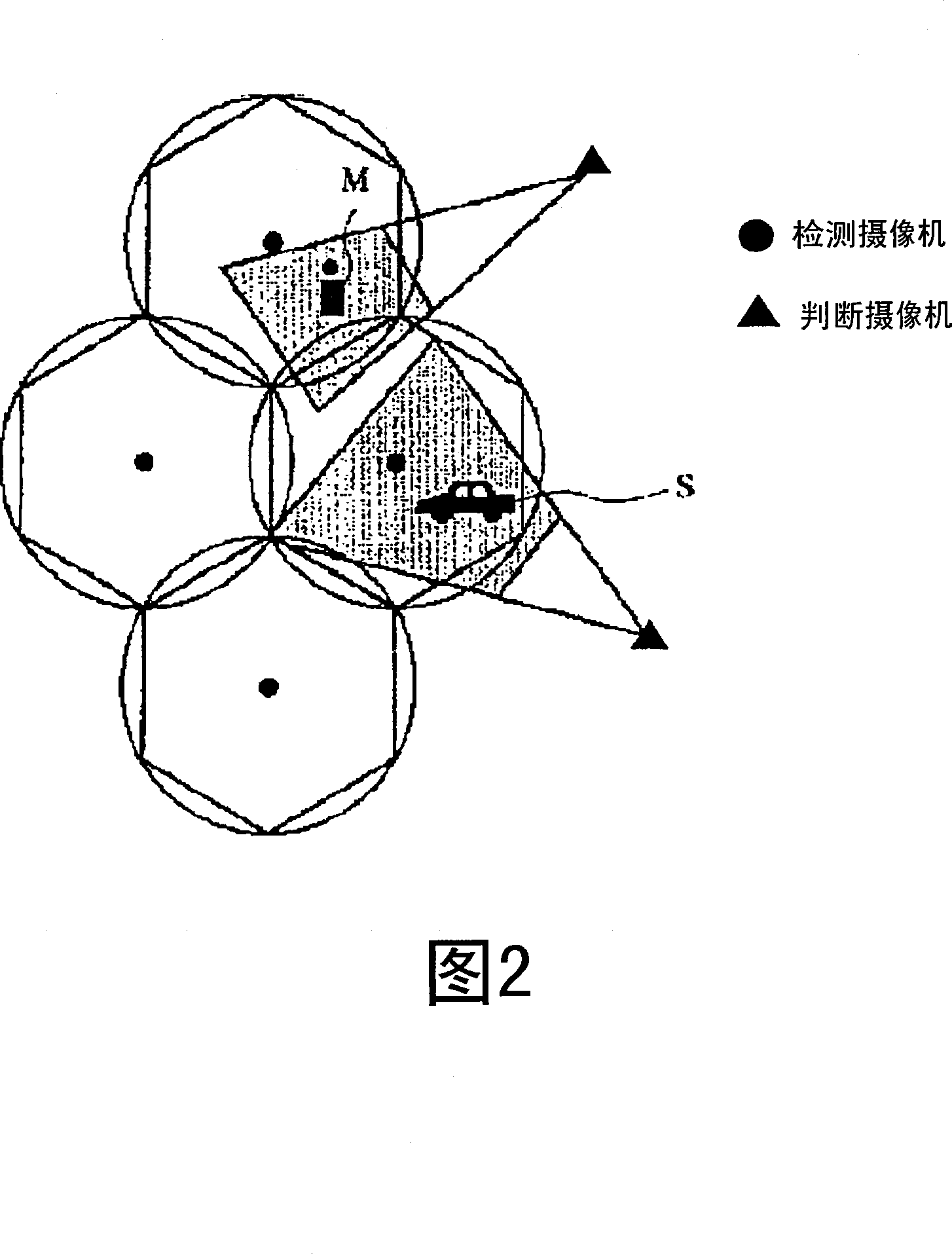
In addition, as shown in FIG. 2 , the judging camera device always repeatedly takes pictures of the area photographed by the detection camera device, so imaging resources such as CCD cannot be effectively utilized.
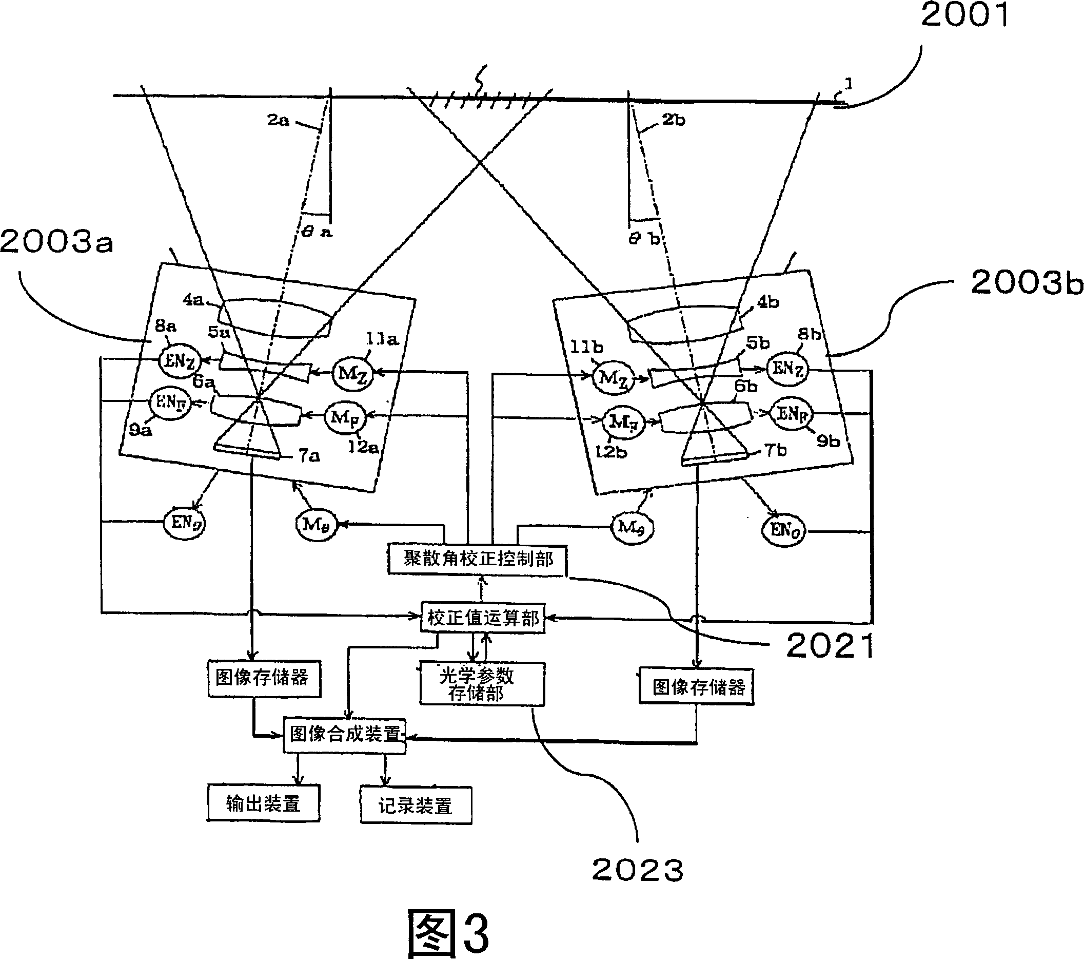
[0016] In addition, in the imaging device of Patent Document 2, it is disclosed that a plurality of cameras with the function of adjusting the vergence angle and the angle of view are used, and in order to create a panoramic image, the overlapped area is kept within a certain range, but it is not considered at all to share the responsibility of the multi-camera. Adjustment of shooting area and resolution of each camera when monitoring the entire surveillance area including multiple important surveillance areas with several moving objects
[0017] In addition, the intrusion monitoring device of Patent Document 3 only discloses that the field of view of the camera that takes pictures of the adjacent area is expanded to include the normal monitoring area of ​​the camera switched to the "tracking" mode. The operation of each camera is not considered
In this way, when expanding the field of view of one camera to include the normal monitoring area of ​​multiple cameras in "tracking" mode, the resolution will be lowered more than necessary.
[0018] In addition, as in the monitoring system of Patent Document 4, since the place where the image is captured or the zoom value is switched according to the purpose, when the camera orientation or zoom is preset for each camera, the preset The setting operation is very complicated
In addition, for moving objects that move irregularly, it is not possible to pre-set

Method used


Image

  • Monitoring system, monitoring method, and camera terminal
  • Monitoring system, monitoring method, and camera terminal
  • Monitoring system, monitoring method, and camera terminal

Examples


Embodiment approach 1

[0096] Embodiments of the present invention will be described below with reference to the drawings.

[0097] First, the configuration of the monitoring system in Embodiment 1 of the present invention will be described.

[0098]FIG. 9 is a diagram illustrating the overall configuration of the monitoring system. The monitoring system of the present invention can perform panning (pan), tilting (tilt), and zooming (zoom) adjustments to indoor halls and living rooms, where the monitoring range is limited to a limited area (hereinafter referred to as the monitoring target area). Shooting of the entire surveillance object area is composed of a sufficient number of camera terminals 101 and 101a and a communication network 102 such as an Ethernet cable for communicating between these camera terminals 101 and 101a. Shooting, tilting, and zooming can be used to adjust the position where the surveillance object area can be photographed.

[0099] 9 is an example of a monitoring system in...

Embodiment approach 2

[0194] Embodiment 2 of the present invention will be described below.

[0195] In the camera terminal 101 of Embodiment 1, the position of the monitored important area is stored in each camera terminal 101 as a resolution weight map, so that the value of the resolution is set between the camera terminals 101 according to the importance of each location. At the same time, it is possible to take pictures of the entire monitoring target area. On the other hand, the camera terminal 201 according to Embodiment 2 prepares a pre-estimated layout figure as a plurality of resolution weight maps 121 for the monitoring target area where the layout figure of a location with high importance for monitoring changes, and selects and uses the resolution weight map 121 according to the situation. And by using it, a monitoring system capable of responding to changes in the layout pattern of places with high monitoring importance is realized.

[0196] First, the configuration of the camera termi...

Embodiment approach 3

[0215] Embodiment 3 of the present invention will be described below.

[0216] In the camera terminal 101 of Embodiment 1, by predetermining the important point of monitoring for each location in the monitoring target area, the monitoring target area is monitored while setting a difference in resolution according to the importance of the location captured by each camera terminal 101. Overall photography.

[0217] On the other hand, in the camera terminal 301 of Embodiment 3, since the monitoring purpose is different, and the monitoring importance depends not on the location being photographed, but on whether there is a predetermined object in the field of view of the camera, By judging the resolution weight based on whether or not the object has been photographed, a surveillance system that photographs the entire surveillance object area is realized while setting a difference in the resolution of each camera terminal 301 according to the existence or position of the object.

...


PUM


Abstract

A monitoring system in which the area to be monitored is fully covered by the imaging areas of camera terminals and imaging with a resolution corresponding to the monitoring importance level distribution is possible. The monitoring system for monitoring the area to be monitored by means of camera terminals (101, 101a) comprises a camera (106) having a function of adjusting its imaging area, a camera control unit (107) for controlling the adjustment of the imaging area of the camera (106), a communication IF (103) for communicating with another camera terminal (101a), and a processing unit (104) for controlling the camera through a camera control unit (107) according to the information on the imaging area of the camera terminal (101a) obtained through the communication IF (103) so that the difference between the weighted resolutions of the imaging areas of the camera terminal (101) and the camera terminal(101a) may be decreased and for thereby adjusting the resolution of the imaging area of the camera terminal (101).

Description

technical field [0001] The present invention relates to a surveillance system composed of a plurality of cameras that can adjust the photographing area by controlling panning, tilting, zooming, etc., and particularly relates to simultaneously photographing the entire surveillance target area at a resolution distributed according to the importance of surveillance Surveillance system for photography. Background technique [0002] In recent years, research and development on a surveillance system using a plurality of cameras mainly for surveillance purposes has been actively conducted. In the monitoring by multiple cameras, strive to meet the following two requirements: for the area to be monitored (surveillance target area) to maintain the state of the blind spot area as little as possible (requirement 1), further, to monitor the important areas in the target area area, to obtain as detailed photographic information as possible (requirement 2). [0003] Among conventional de...

Claims


Application Information

Patent Timeline
Patent Type & Authority Applications(China)
IPC IPC(8): H04N7/18H04N5/232H04N5/225
CPCH04N5/232H04N5/23238H04N5/23245H04N7/181H04N7/185H04N23/667H04N23/698H04N23/695
Inventor 吉田笃青木胜司荒木昭一
Owner PANASONIC CORP
Why Eureka
Try Eureka