Spring clamp

A spring clip and base technology, applied in the field of spring clips, can solve the problems of unsightly appearance, scratches, waste of packaging space, etc., and achieve the effects of reducing shipping costs, preventing scratches, and saving packaging space

Inactive Publication Date: 2007-10-31
LECO STATIONERY MFG CO LTD
View PDF0 Cites 6 Cited by
  • Summary
  • Abstract
  • Description
  • Claims
  • Application Information

AI Technical Summary

Problems solved by technology

On the one hand, these lugs will leave gaps between adjacent spring clips during packaging, wasting packaging space; Cause scratches and affect product sales
In addi

Method used


Image

  • Spring clamp
  • Spring clamp
  • Spring clamp

Examples


Example Embodiment

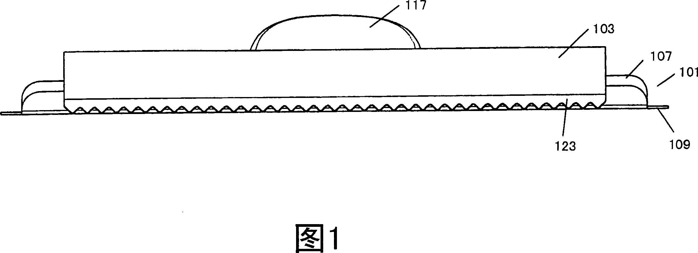
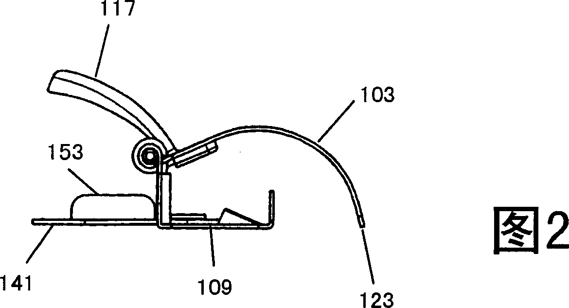
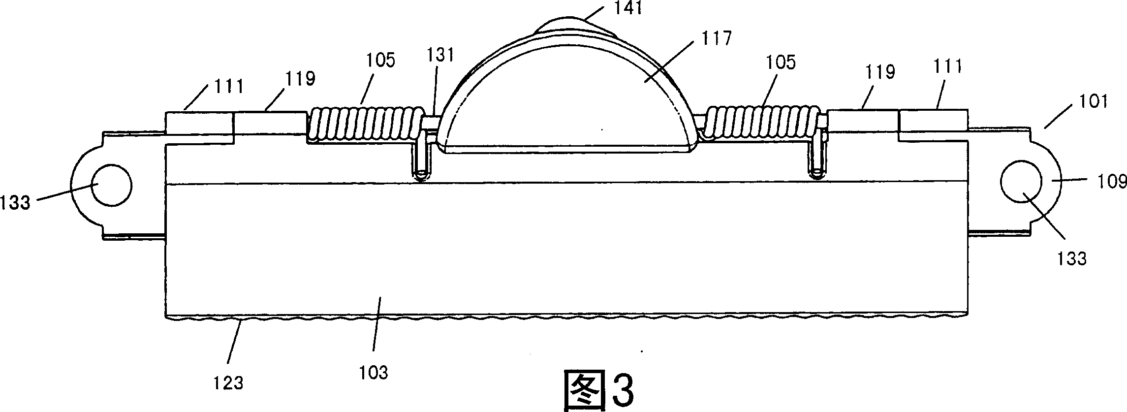
[0040] As shown in FIGS. 1-9, the spring clip 100 according to the first embodiment of the present invention generally includes a base 101, a pressing portion 103, and a spring 105. The base 101 is formed in such a way that the elongated sheet is bent at about 90 degrees to form an upwardly standing side wall 107 and a horizontally extending bottom wall 109. The upper edge of the side wall 107 of the base 101 forms at least two lugs 111 with through holes 113 that are turned outwards. The pressing portion 103 is formed by bending an elongated sheet into an arc shape. A pressing handle 117 extending outward and upward is formed at the middle of the longitudinal inner edge of the pressing portion 103 that is engaged with the base 101, and at least two pressing handles 117 are formed on both sides of the pressing handle 117 on the longitudinal inner edge of the pressing portion 103. Rolled up lugs 119 with through holes 121. In order to clamp the paper sheet tightly, the longitudinal...


PUM


Abstract

The invention relates to a spring clamp that comprises the base and compression part that can be installed together in motion, with the compression part lean against the base tightly under the action of the spring, with the suspension spring clamp hanger being able to be installed to the base of the said base. It can select whether to expose the hanger from the body of the spring clamp or hide it.

Description

Technical field [0001] The invention relates to a spring clip. Background technique [0002] Spring clips are widely used to clamp and hold paper sheets. In actual use, the spring clip is often fixed to a rigid board or the bottom plate of a file by at least one rivet to form a complete file. In use, sometimes the file folder needs to be hung, so it is necessary to set hanging ears on the spring clip. The hanging ears of the existing spring clip are usually fixed or movable hanging ears arranged on the main body of the spring clip and almost completely exposed outside the main body. On the one hand, these hanging ears will leave a gap between adjacent spring clips during packaging, which wastes the packaging space; on the other hand, some hanging ears are always in a freely movable state, and their random activities may give adjacent spring clips Cause scratch marks and affect product sales. In addition, when there is no need to hang the spring clip, the hanging ears are always e...

Claims


Application Information

Patent Timeline
IPC IPC(8): B42F1/02B42F9/00
CPCB42F1/006B42F9/001
Inventor 林春海
Owner LECO STATIONERY MFG CO LTD
Why Eureka
Try Eureka