Magnetic gage stand arrangement used for precision measurement

A magnetic base and precision measurement technology, applied in the direction of measuring devices, measuring gauges, measuring instrument components, etc., can solve problems affecting measurement, affecting measurement accuracy, unstable support rods, etc., and achieve strong resistance to external vibrations and other interference , reduce mechanical deformation, convenient and quick measurement

Inactive Publication Date: 2007-10-31
WUHAN UNIV OF TECH
View PDF0 Cites 5 Cited by
  • Summary
  • Abstract
  • Description
  • Claims
  • Application Information

AI Technical Summary

Problems solved by technology

The adsorption force of each magnetic watch base is determined by its internal permanent magnet, so the existing magnetic watch base has an unadjustable adsorption force and cannot meet various needs for adsorption capacity.
In addition, the base and the support rod are connected by a movable connection device, and the support rod is not fixed stably, which is prone to shaking and affects the measurement accuracy
[0007] 2. The existing magnetic base has insufficient ability to resist external interference
The volume and weight of the object to be measured are generally relatively large, and most of them are rigidly transmitted. Therefore, when the base 1 and the object to be measured are vibrated by external interference at the same time, their ability to transmit vibration is not the same, and then the measuring instrument or the probe. Vibration is greatly amplified relative to the measured object, which greatly affects the accuracy of measurement, and due to the influence of vibration, the measured value cannot be quickly stabilized, causing inconvenience in data collection
[0008] 3. The adjustment of the existing fine-tuning head 3 is inconvenient, and after each adjustment, due to the mechanical deformation of the fine-tuning head 3 and the vibration at the top of the cantilever beam, it is difficult to quickly stabilize the value of the measuring instrument, and even cause the measured value to slow down. drift
Measuring instruments or probes are clamped at the fine-tuning head 3, and each adjustment is always realized by tightening the screws. Since the fine-tuning head 3 is elastic, the fine-tuning head 3 always deforms slowly after adjustment, and it takes a long time to stabilize. It is inconvenient to operate and affects the measurement
However, due to the need to tighten the screws during adjustment, a large force acts on the top of the cantilever beam, causing the cantilever beam to vibrate, which also affects the accuracy of the measurement.

Method used


Image

  • Magnetic gage stand arrangement used for precision measurement
  • Magnetic gage stand arrangement used for precision measurement
  • Magnetic gage stand arrangement used for precision measurement

Examples


Embodiment Construction

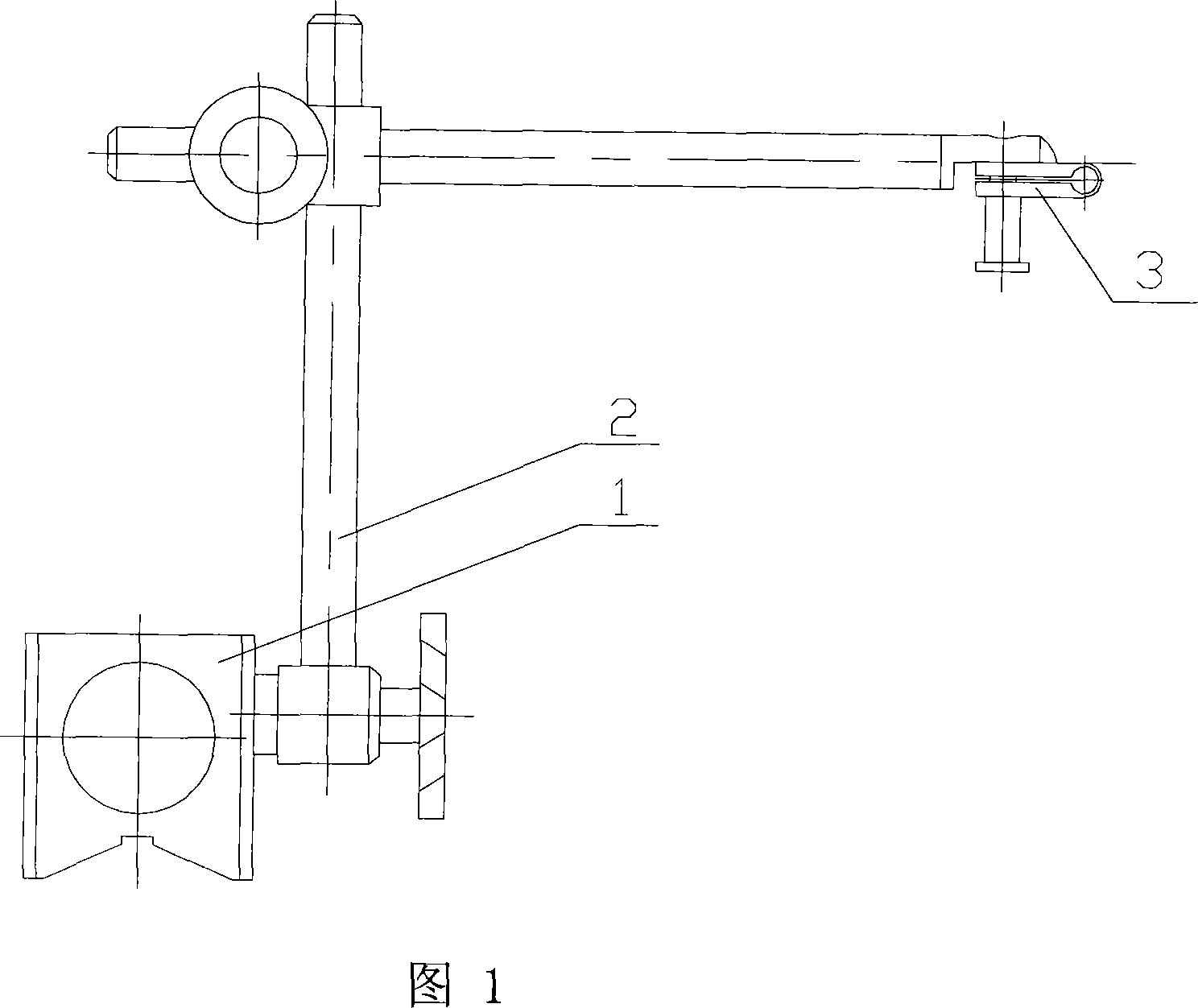
[0022] As shown in Figure 4 and Figure 5, a magnetic table base device for precision measurement, it includes a base 1, a support rod 2, a fine-tuning head 3, and a beam 11, the fine-tuning head 3 is set on the fine-tuning screw, and the fine-tuning screw passes through The elongated fine-tuning screw sliding hole on the crossbeam 11, the fine-tuning screw below the crossbeam 11 is screwed with nut 12, and the fine-tuning screw above the crossbeam 11 is screwed with nuts (tighten 2 nuts on the fine-tuning screw, the fine-tuning screw and the crossbeam 11 fixed connections). The two ends of the beam 11 are respectively fixedly connected with a sliding sleeve 10, and the two sliding sleeves 10 are respectively set on the upper end of a support rod 2, and the sliding sleeve 10 is provided with a fastening screw 9 (the two ends of the sliding sleeve 10 can be opened, Screw holes are respectively arranged at both ends, and the fastening screw 9 is screwed into two screw holes; or a...


PUM


Abstract

This invention relates to one magnetic socket device, which comprises socket, supportive bar and micro adjuster and is characterized by the following: the micro adjust probe is set on beam with two parts fixed on one slide cover with each one covered on supportive bar top end and two down end fixed on one socket; the base socket is composed of seat, spiral coil, aluminum coils skeleton and connection screw nail; the spiral coil is around aluminum skeleton on the skeleton chamber fixed by connection nail with two ends connected to wire through wire hole and power.

Description

technical field [0001] The invention relates to a magnetic watch stand device. Background technique [0002] The magnetic base device refers to the support for clamping measuring instruments such as thousand (hundred) indicators, lever thousand (hundred) indicators, etc., and can also be used as a probe clamping support for micro-displacement measuring instruments. It uses the controllable magnetic force of the base to firmly absorb on the plane of other iron objects for work. The magnetic force comes from the magnetic field source generated by the permanent magnet in the base. The magnetic table base device is easy to operate and easy to use, and is suitable for measurement in various occasions. It is widely used to measure the shape error and position error of the workpiece, and can measure the accurate value easily and quickly. [0003] The existing magnetic table base device is shown in FIG. 1 , which includes a base 1 , a support rod 2 , a suspension rod, and a fine-...

Claims


Application Information

Patent Timeline
Patent Type & Authority Applications(China)
IPC IPC(8): G01B3/22G01D11/00
Inventor 陈定方赵亚鹏卢全国舒亮陈敏陶孟仑甄玉云沈琛林钟毓宁
Owner WUHAN UNIV OF TECH
Why Eureka
Try Eureka