Light shield and method for forming air-cushion surface pattern on surface of magnetic head using same

An air cushion surface and photomask technology, which is applied to the hydrodynamic spacing of the head, the configuration/installation of the recording head, the support head, etc., can solve the problem that the gap between the long strips cannot be shortened sufficiently, the production efficiency of the lithography machine cannot be improved, and the long-term The number of strips cannot be increased, etc., to achieve the effects of increasing the output of magnetic heads, saving materials, and improving processing efficiency

Inactive Publication Date: 2007-10-31
SAE MAGNETICS (HK) LTD
View PDF0 Cites 2 Cited by
  • Summary
  • Abstract
  • Description
  • Claims
  • Application Information

AI Technical Summary

Problems solved by technology

Therefore, in the conventional technology, the gap between the strips cannot be shortened sufficiently, so that the air bearing surface with high precision cannot be formed on the magnetic head; The output of the magnetic hea

Method used


Image

  • Light shield and method for forming air-cushion surface pattern on surface of magnetic head using same
  • Light shield and method for forming air-cushion surface pattern on surface of magnetic head using same
  • Light shield and method for forming air-cushion surface pattern on surface of magnetic head using same

Examples


Example Embodiment

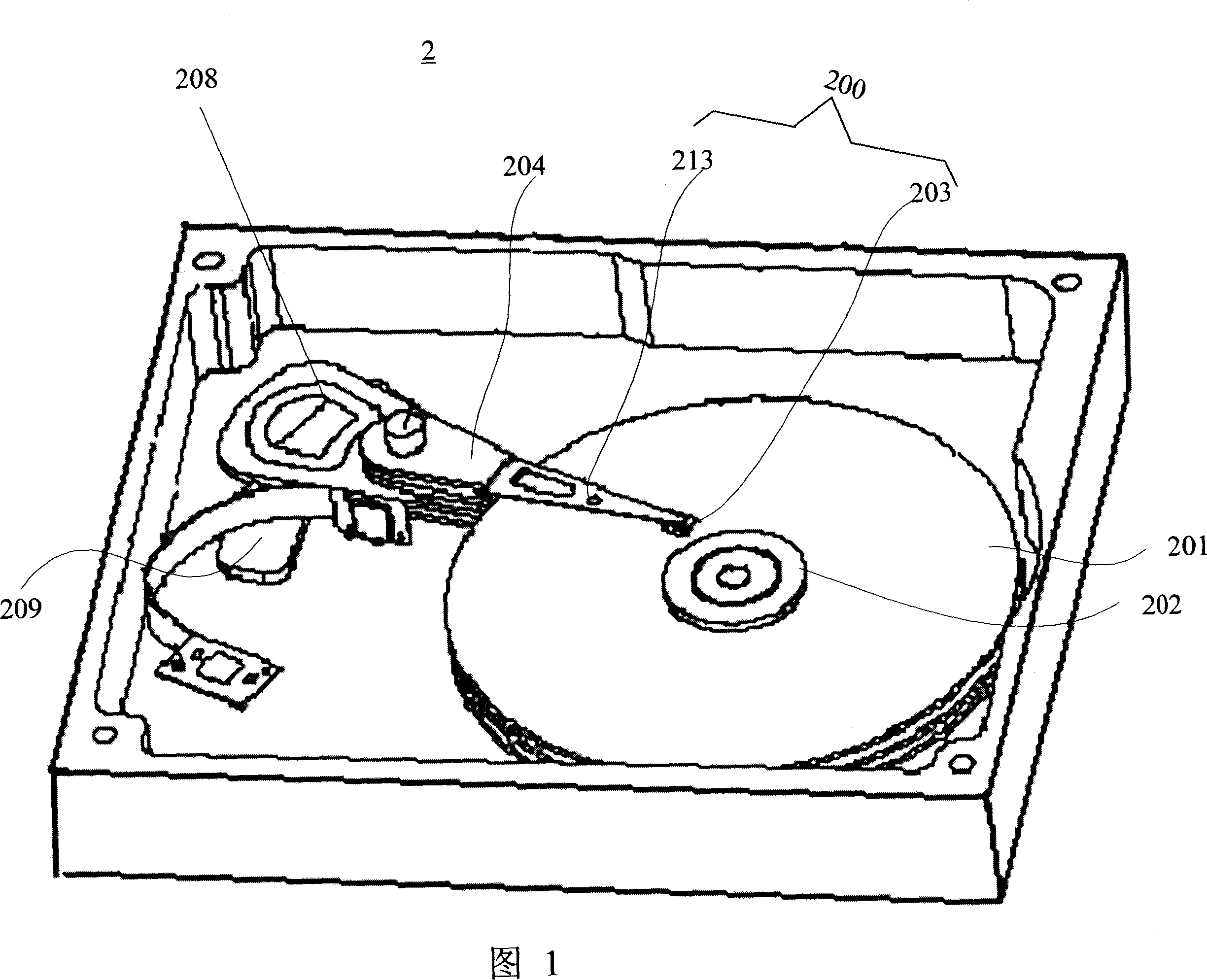
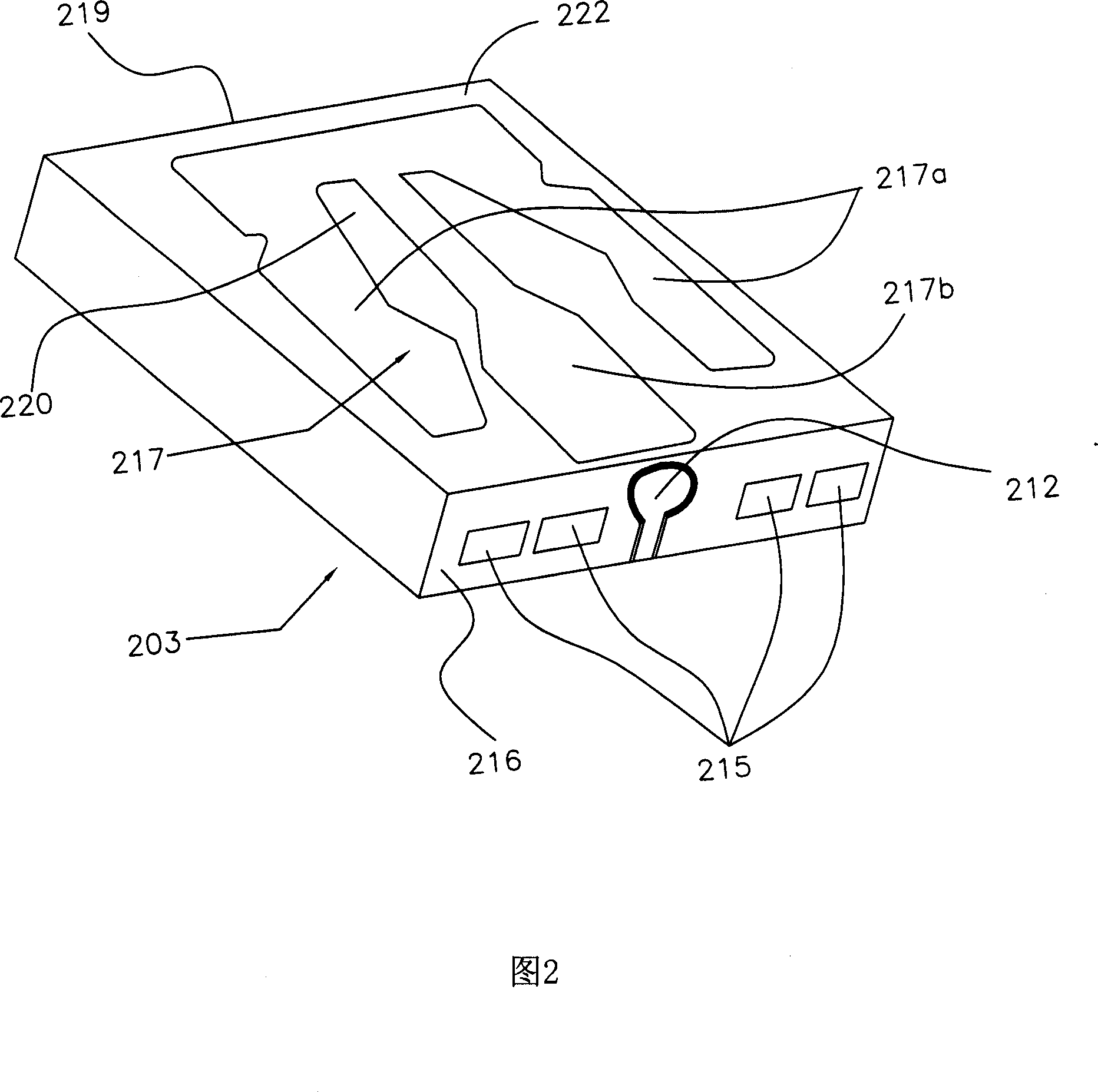
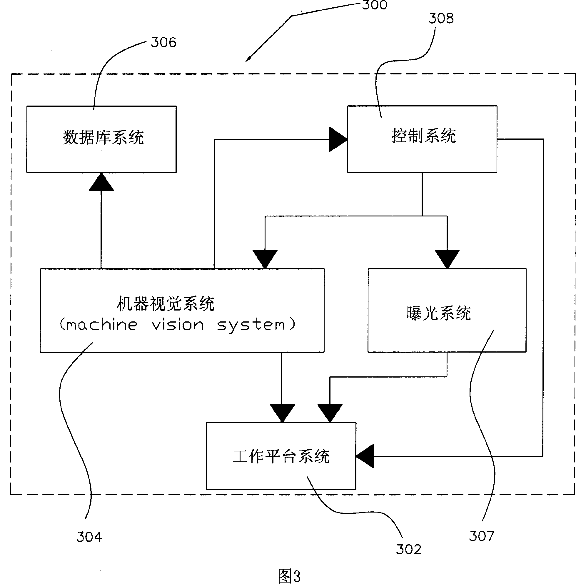
[0047] Embodiments of the present invention will now be described with reference to the accompanying drawings. The invention provides a photomask, comprising: a base and a metal thin film layer formed on the base. An air bearing surface image, a mask mark and a machine vision system window are formed on the metal thin film layer. Wherein, the window of the machine vision system is coincident with the image of the air bearing surface. The invention uses the light-transmitting central air-bearing surface image with a large outline on the reticle as the window of the machine vision system, avoiding the design of the machine vision system window with a small outline that exists independently in the traditional reticle, and at the same time forming a small size on the reticle. The reticle logo of the reticle replaces the oversized reticle logo in the traditional reticle. Through the cooperation between the window of the machine vision system and the reticle mark, the long strip c...


PUM

PropertyMeasurementUnit
Widthaaaaaaaaaa
Widthaaaaaaaaaa

Abstract

This invention provides one light cover, which comprises transparent base and metal film layer on base, wherein the metal film layer forms ABS image for light, reticle key and MVS window and the window and the ABS image are overlapped. This invention also provides one ABS pattern method on magnetic head surface by use of the cover.

Description

technical field [0001] The present invention relates to a method and device for manufacturing a disk drive unit, and more particularly to a photomask and a method for forming an air bearing surface pattern on the surface of a magnetic head of a disk drive unit by using the photomask. Background technique [0002] A common information storage device is a disk drive system, which uses a magnetic medium to store data and selectively read data from or write data to the magnetic medium by means of a removable read / write head disposed over the magnetic medium. on magnetic media. [0003] FIG. 1 is a perspective structural view of a conventional disk drive unit 2. A disk 201 is mounted on and rotated by a spindle motor 202. As shown in FIG. A head gimbal assembly (HGA) 200 is connected to the drive arm 204 . The magnetic head gimbal assembly 200 includes a magnetic head 203 mounted with a read-write head and a cantilever member 213 supporting the magnetic head 203 . A voice coil...

Claims


Application Information

Patent Timeline
IPC IPC(8): G11B5/60G11B21/21G11B5/84
Inventor 金则清尹辉肖爱龙
Owner SAE MAGNETICS (HK) LTD
Why Eureka
Try Eureka