Display device module

A display device and device-driven technology, which is used in the direction of identification devices, instruments, electroluminescence light sources, etc.

Inactive Publication Date: 2007-10-31
LG DISPLAY CO LTD
View PDF0 Cites 12 Cited by
  • Summary
  • Abstract
  • Description
  • Claims
  • Application Information

AI Technical Summary

Problems solved by technology

Correspondingly, although the device driver unit 11 is not installed on the substrate 10, the luminescence inspection and aging treatment can also be performed

Method used


Image

  • Display device module
  • Display device module
  • Display device module

Examples


Embodiment Construction

[0035] Hereinafter, preferred embodiments of the present invention will be described in detail with reference to the accompanying drawings. In the following embodiments, an organic electroluminescent device is provided as an example of a light-emitting device. However, it is clear that the teaching of the present invention is not limited to organic electroluminescent devices.

[0036] An organic electroluminescent device (hereinafter referred to as a "panel") includes at least one light-emitting region formed by at least one anode electrode ("first electrode") formed on a substrate on which an organic electroluminescent A light-emitting light-emitting layer and at least one cathode electrode ("second electrode") formed on the organic electroluminescent light-emitting layer. Here, the order of forming the cathode electrode and the anode electrode may be reversed to the order of forming the above-mentioned structures.

[0037] On the other hand, the substrate on which the abov...


PUM


Abstract

The present invention discloses the display device module in which the first and second lines can be connected easily to a device-driving unit or a connecting means on which the device-driving unit is mounted, the display device module of the present invention comprises a pixel circuit section including at least one light emitting area, each light emitting area being formed at an overlying area of a substrate between a first electrode and a second electrode on a substrate; at least one first line being electrically connected to the first electrode in the pixel circuit section; at least one second line being electrically connected to the second electrode in the pixel circuit section, wherein each of the first lines and the second lines has a connecting portion formed thereon and the connecting portion is larger than the line in the width, the connecting portions are alternated with the connecting portion(s) of the neighbor line(s) so as to prevent two adjacent connecting portions from being contacted with each other.

Description

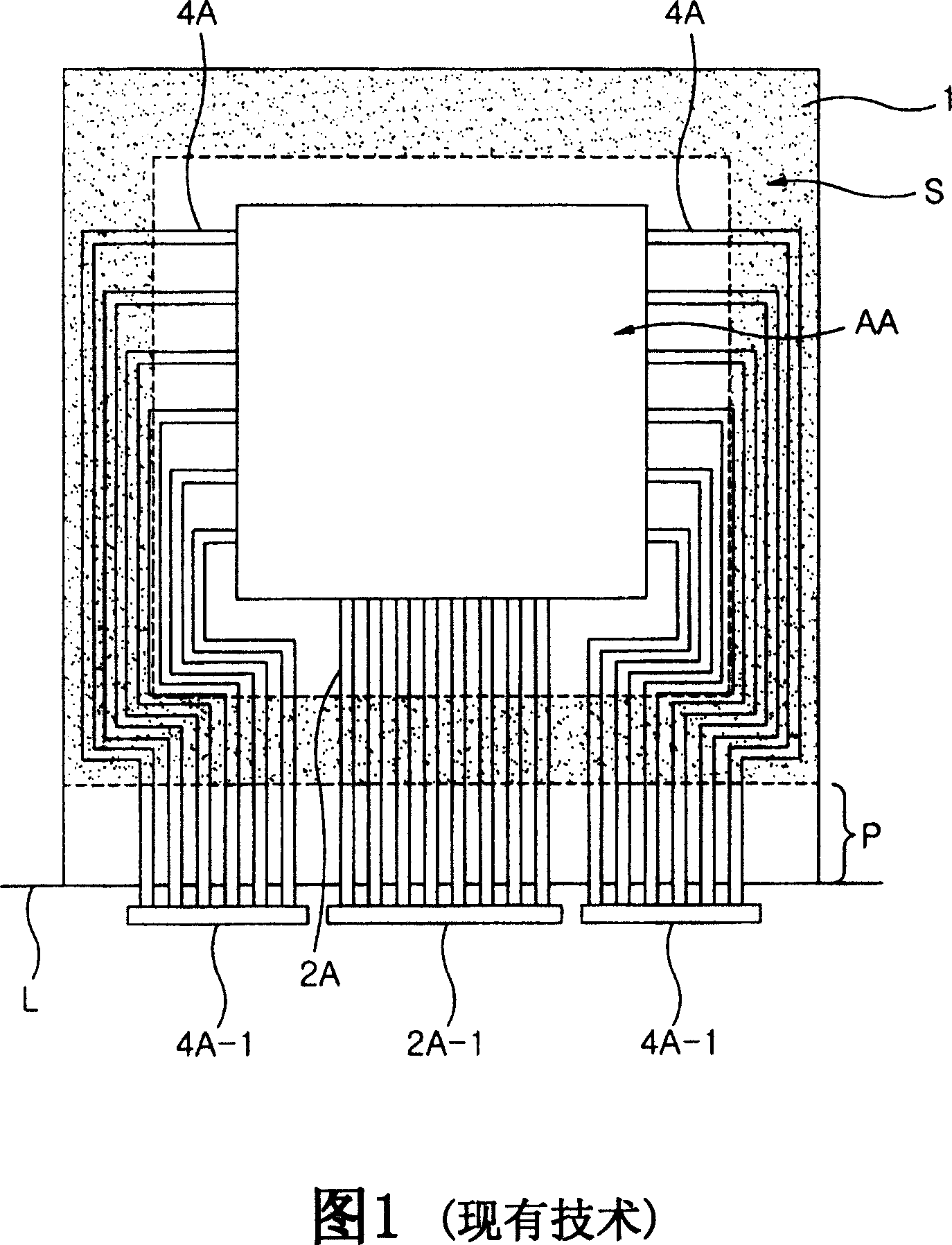
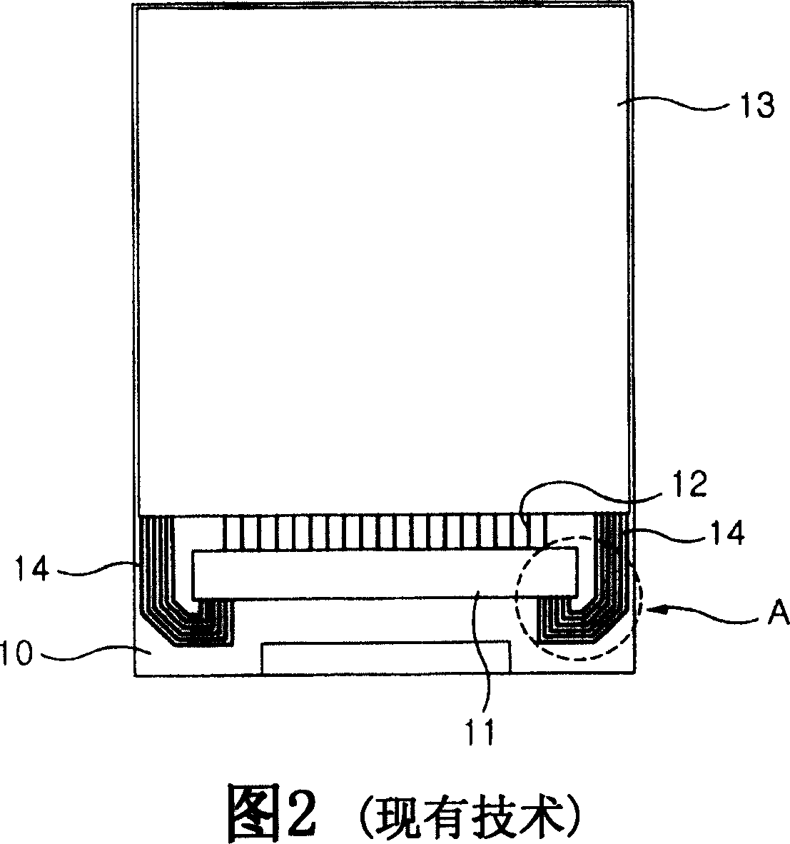
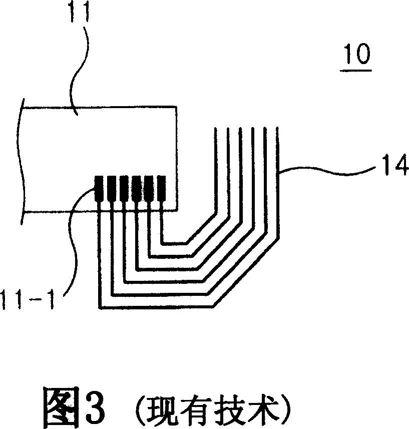
technical field [0001] The present invention relates to a display device module, in particular to a display device module in which metal wires are effectively arranged on a substrate and the metal wires are easily contacted with pins or fixtures. Background technique [0002] FIG. 1 is a plan view of a conventional organic electroluminescent device including a pixel circuit portion, wherein a conventional organic electroluminescent device with an outer cover removed is depicted in FIG. 1 for convenience. [0003] On the other hand, only one pixel circuit part among a plurality of pixel circuit parts formed on the main substrate is described in the frame of FIG. 1, and the pixel circuit part AA includes an anode electrode formed on the substrate, a The formed organic electroluminescent light-emitting layer and the cathode electrode formed on the organic electroluminescent light-emitting layer. [0004] The data line 2A and the scan line 4A formed on the main substrate are re...

Claims


Application Information

Patent Timeline
Patent Type & Authority Applications(China)
IPC IPC(8): H01L27/32H01L27/15H01L23/522G09F9/30
CPCH01L27/3288H01L27/3276H10K59/179H10K59/131H05B33/26
Inventor 李一镐
Owner LG DISPLAY CO LTD
Why Eureka
Try Eureka