Supercharge Your Innovation With Domain-Expert AI Agents!

Dc-to-dc converter and electric motor drive system using the same

A technology of DC converter and converter, which is applied in the direction of DC motor speed/torque control, conversion of DC power input to DC power output, control system, etc., and can solve the problems of increased manufacturing cost and other issues

Inactive Publication Date: 2007-10-31
FORD GLOBAL TECH LLC
View PDF0 Cites 15 Cited by
  • Summary
  • Abstract
  • Description
  • Claims
  • Application Information

AI Technical Summary

Problems solved by technology

The use of these well-matched or higher voltage rated capacitors generally results in increased manufacturing costs for the controller 20

Method used


Image

  • Dc-to-dc converter and electric motor drive system using the same
  • Dc-to-dc converter and electric motor drive system using the same
  • Dc-to-dc converter and electric motor drive system using the same

Examples


Embodiment Construction

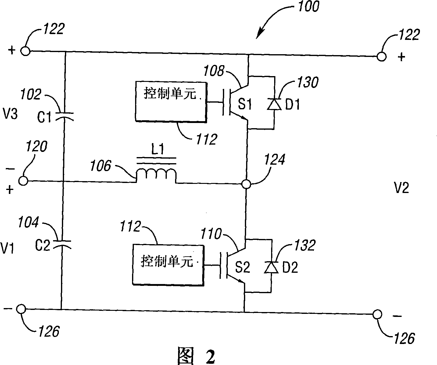
[0015] Referring to FIG. 2 , it shows a schematic diagram of a DC-DC converter 100 according to at least one embodiment of the present invention. The converter 100 generally comprises a first capacitor (ie C1) 102, a second capacitor (ie C2) 104, an inductor (ie L1) 106, a first switching device (ie S1) 108, a second switching device (ie S2 ) 110, and a plurality of nodes, such as a first node 120, a second node 122, a third node 124, and a fourth node 126.

[0016] First capacitor 102 (i.e., capacitive element), second capacitor 104, and inductor 106 (i.e., inductive element) may each include a circuit breaker for connecting the respective component (i.e., 102, 104, and / or 106) to an adjacent component. first and second terminals (ie, electrical connection points). Likewise, the first 108 and / or second 110 switching devices (ie, switches) may each include first and second terminals connecting the respective switches (ie, 108 and / or 110 ) to adjacent components.

[0017] In ...


PUM


Abstract

A DC-to-DC converter and to an electric motor drive system using the same. The DC-to-DC converter includes first and second capacitors, an inductor, and first and second switching devices.

Description

technical field [0001] The present invention generally relates to a DC-DC converter and a motor drive system using the same. Background technique [0002] A DC-DC converter generally converts (ie converts) a direct current voltage ("DC") from a first voltage level to a second voltage level. A DC-DC converter that transforms a lower input voltage into a higher output voltage (ie, boosted voltage) may be referred to as a "boost" converter. Likewise, a DC-DC converter that converts a higher input voltage to a lower output voltage (ie, steps down the voltage) may be referred to as a "buck" converter. [0003] Referring to FIG. 1( a ), it shows a schematic diagram of a conventional bidirectional DC-DC converter 10 . Generally, Va, Vb and Vc represent three possible terminal voltages, Vb is greater than or equal to Va (ie Vb≥Va), and Vc is equal to the difference between Vb and Va (ie Vc=Vb-Va). A conventional DC-DC converter 10 is bidirectional, so any one of Va, Vb or Vc can ...

Claims


Application Information

Patent Timeline
Patent Type & Authority Applications(China)
IPC IPC(8): H02M3/06H02M3/155H02P7/292
CPCH02M2001/007H02M3/158H02M1/0093H02M1/007H02M3/155H02M3/1582
Inventor 陈清麒文凯特斯瓦·桑卡兰迈克尔·德格内尔
Owner FORD GLOBAL TECH LLC
Features
  • R&D
  • Intellectual Property
  • Life Sciences
  • Materials
  • Tech Scout
  • Unparalleled Data Quality
  • Higher Quality Content
  • 60% Fewer Hallucinations
Learn More