Egr control device for internal combustion engine

A technology for control devices and internal combustion engines, applied in engine control, internal combustion piston engines, electrical control, etc., can solve difficult problems such as system simplification and matching difficulties

Inactive Publication Date: 2007-10-31
MITSUBISHI FUSO TRUCK AND BUS CORPORATION
View PDF1 Cites 8 Cited by
  • Summary
  • Abstract
  • Description
  • Claims
  • Application Information

AI Technical Summary

Problems solved by technology

However, this necessitates matching the control gains involving both the insensitive region and the reactive region, and since the matching itself is difficult, it is difficult to achieve system simplification
Therefore, some measures need to be taken for the switching of the control between the EGR valve and the throttle valve, but in the prior art described above, this is not specifically considered

Method used


Image

  • Egr control device for internal combustion engine
  • Egr control device for internal combustion engine
  • Egr control device for internal combustion engine

Examples


Embodiment Construction

[0015] Embodiments of the present invention will be described below with reference to the drawings.

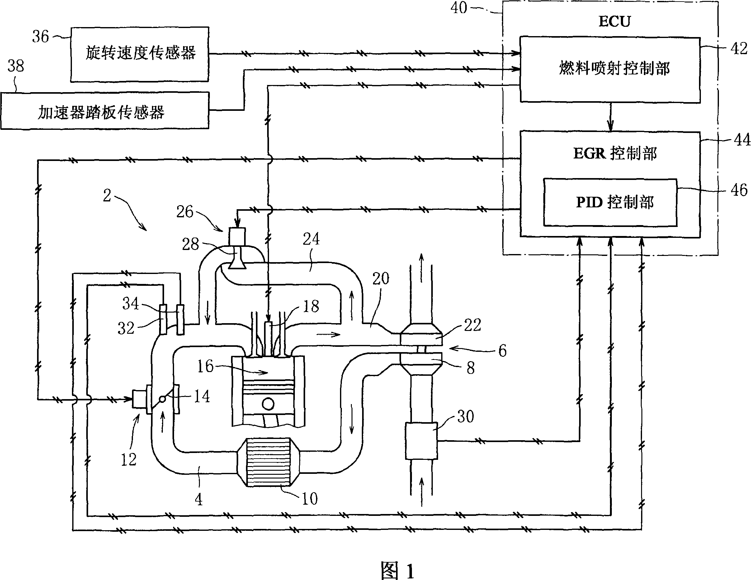
[0016] Fig. 1 is an embodiment of an EGR control device for a diesel engine. As shown in the figure, a supercharger 6 is provided in the intake passage 4 of the engine 2 . Intake air taken from an air cleaner (not shown) is pressurized by compressor 8 and introduced into combustion chamber 16 via intercooler 10 .

[0017] In addition, an intake throttle valve 12 is provided at an appropriate position in the passage 4 . The throttle valve 12 has a butterfly valve body 14 driven by a brushed motor, and the flow rate of the intake air is controlled by the opening and closing of the valve body 14, and the recirculation amount of the exhaust gas (EGR) as described later is also controlled. quantity). In this way, in the throttle valve 12 of the present embodiment, a current flows in a diagram in which a magnetic field is generated using a brush.

[0018] A turbine 22 is provide...


PUM


Abstract

An EGR control device for an internal combustion engine has an EGR control means (44) that, when a large amount of EGR is required, continuously controls the opening of an EGR valve (26) in a fully open direction and continuously controls the opening of a suction throttle valve (12) in a fully closed direction. In an insensible region in which variation in the amount of EGR is small relative to the opening of the suction throttle valve, the control means applies limitation to feedback control of the amount of EGR carried out by the suction throttle valve and performs, on the other hand, feedback control of an EGR amount carried out by the EGR valve to supplement the limited feedback control by the suction throttle valve.

Description

technical field [0001] The present invention relates to an EGR control device for an internal combustion engine requiring a large amount of exhaust gas recirculation (EGR). Background technique [0002] In such an apparatus, a part of the exhaust gas is returned to the intake passage via the passage for EGR (EGR passage) and supplied to the combustion chamber. In addition, by feedback-controlling the exhaust gas recirculation amount (EGR amount), it is possible to ensure a good combustion state and to promote exhaust gas purification. [0003] Here, in the conventional device, only the opening degree of the EGR valve that controls the flow rate in the EGR passage is controlled. However, in recent internal combustion engines, operation with a large amount of EGR (high EGR rate) is required. Therefore, in addition to the EGR valve described above, the opening degree of the intake throttle valve that controls the flow rate in the intake passage is also adjusted (see Japanese ...

Claims


Application Information

Patent Timeline
Patent Type & Authority Applications(China)
IPC IPC(8): F02D21/08F02M25/07
CPCF02D2041/0017Y02T10/47F02M25/0713F02D11/10F02D41/0065F02M25/0707F02B29/0406F02M26/05F02M26/10Y02T10/40F02D9/04F02D21/08
Inventor 琴冈正二郎纐缬晋横村仁志
Owner MITSUBISHI FUSO TRUCK AND BUS CORPORATION
Why Eureka
Try Eureka