
Jack catch and clamping device and turnover device

A technology of overturning device and claws, which is applied in the field of clamping devices, overturning devices, and claws. It can solve the problems of difficult grasping by operators, damage to magnetic heads, and low installation efficiency, so as to facilitate accurate positioning and ensure accurate positioning. , high work efficiency

Inactive Publication Date: 2010-11-17
YITUO SCI & TECH CO LTD SHENZHEN
View PDF5 Cites 0 Cited by
  • Summary
  • Abstract
  • Description
  • Claims
  • Application Information

AI Technical Summary

Problems solved by technology

Due to the integration of a large number of parts in the hard disk with limited space, and the special shape of these parts, it is difficult for the operator to grasp directly by hand, which puts forward extremely high requirements for the accurate positioning and installation of various parts. It is difficult to meet the process requirements with the claw device
Especially when installing various magnetic components with simple tools or installing metal components in places where there is a magnetic field, due to the attractive force of the magnetic field, it brings great inconvenience to the accurate positioning and installation of the components, and sometimes even damages other parts or causes Mutual damage, installation efficiency is very low
For example, when installing the upper and lower disks of the upper and lower magnetic head fans, the magnetic field attraction is quite strong when the upper and lower disks are close to the fan tails. It is difficult to accurately position and install the disks by hand, and it is slightly less Be careful, it can also damage the heads

Method used


Image

  • Jack catch and clamping device and turnover device
  • Jack catch and clamping device and turnover device
  • Jack catch and clamping device and turnover device

Examples


Embodiment Construction

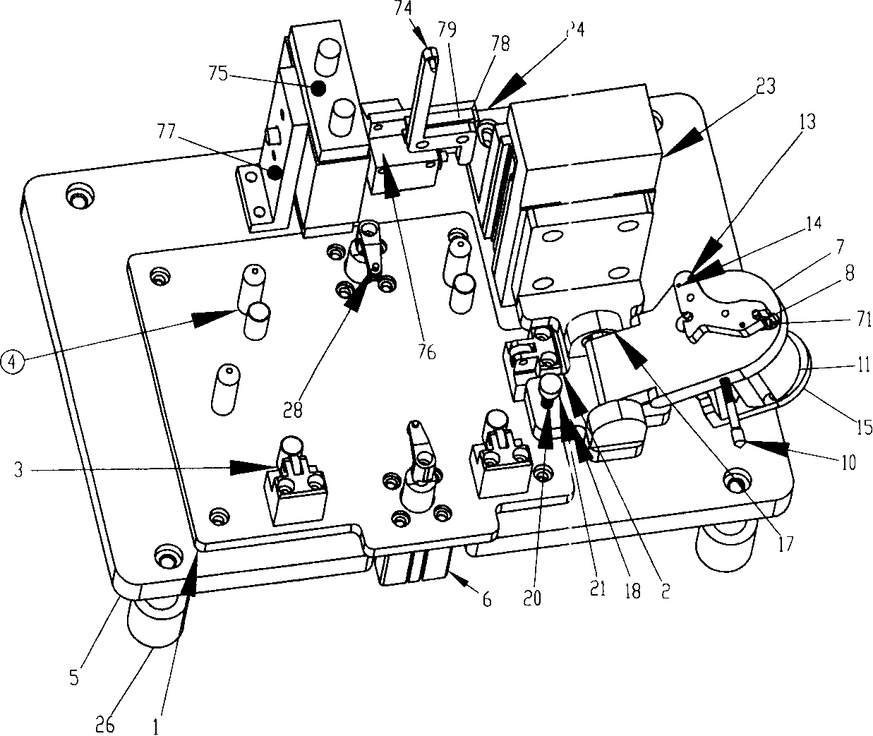
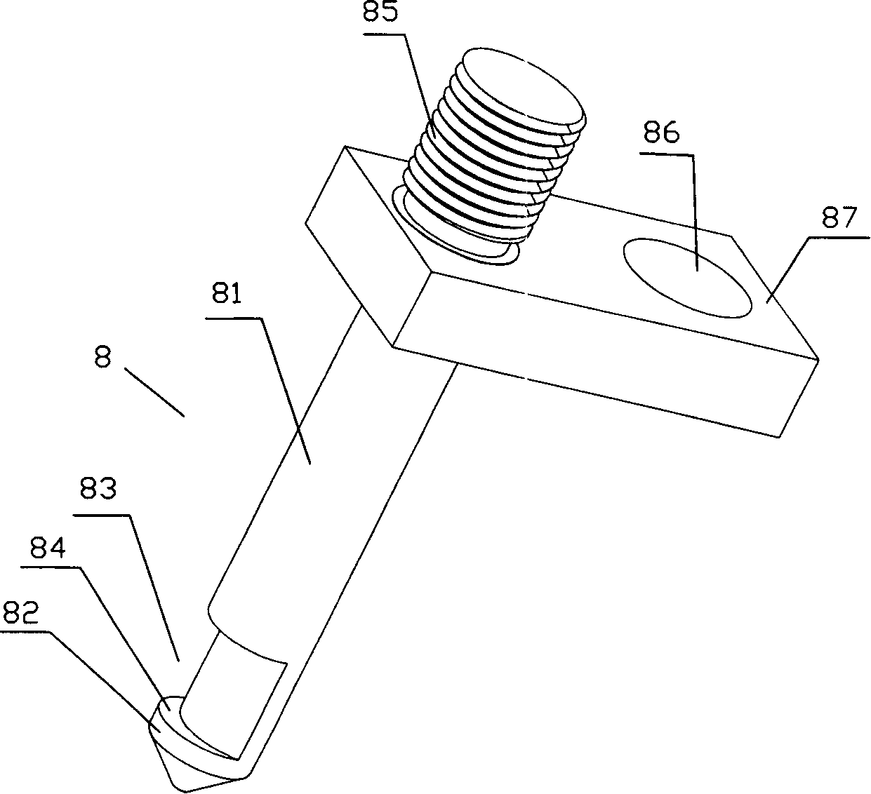
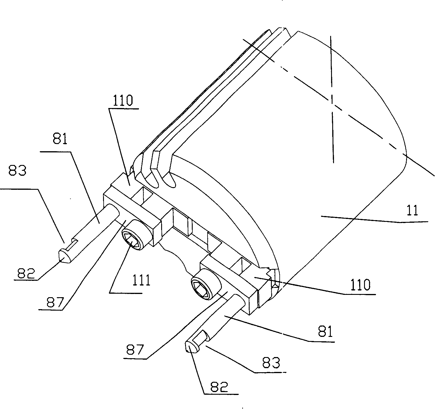
[0023] A turning device such as figure 1 , figure 2 and image 3 As shown, it includes a clamping device, a base plate 5, a tooling panel 1 fixed on the base plate 5, and a displacement adjustment device. The clamping device includes a claw 8, a lifting cylinder 23 fixed on the base plate 5, and is fixedly connected with the lifting cylinder 23. The turnover plate seat 17, the turnover plate 7 rotatably supported on the turnover plate seat 17, and the turnover adjustment plate 18 fixedly connected with the turnover plate seat 17. Open at least a pair of positioning holes 71 on the turnover plate 7, each stretch out a claw 8 in each positioning hole 71, the claw 8 includes a clamping rod 81 and a fixed block 87, the top of the clamping rod 81 has a clamping head 82, the clamping head There is an arc-shaped notch 83 on the 82, and a boss 84 supporting the clamping parts is formed below the arc-shaped notch 83 near the top. The part of block 87 is threaded rod 85, and there i...


PUM


Abstract

This invention relates to a claw and a tightening device including a claw rod, a drawing-in gear and a fixing block set on top of the rod, in which, an arc gap is set on the gear, which has a protruding desk supporting clamp parts, the bottom of the rod is fixedly connected with the fixing block and the part extending from the fixing part is a screw thread rod and a fixing cover hole is set on the fixing block.

Description

technical field [0001] The invention relates to a claw, a clamping device and a flipping device, which are suitable for accurate positioning and installation of various components, and are especially suitable for accurate positioning and installation of magnetic elements (magnet sheets) on the upper and lower sides of a hard disk induction coil. Background technique [0002] With the development of hard disk technology, the size of hard disk is getting smaller and smaller. Due to the integration of a large number of parts in the hard disk with limited space, and the special shape of these parts, it is difficult for the operator to grasp directly by hand, which puts forward extremely high requirements for the accurate positioning and installation of various parts. It is difficult to meet the process requirements with the claw device. Especially when installing various magnetic components with simple tools or installing metal components in places where there is a magnetic fie...

Claims


Application Information

Patent Timeline
Patent Type & Authority Patents(China)
IPC IPC(8): G11B33/00G11B5/127H05K13/04B23P21/00
Inventor 李源海
Owner YITUO SCI & TECH CO LTD SHENZHEN
Learn More