Mobile driving mechanism

A power source, mobile technology, applied in the direction of vacuum cleaner storage devices, cleaning equipment, vacuum cleaners, etc., to achieve the effect of reliable protection and placement

Inactive Publication Date: 2007-11-07
ROBERT BOSCH GMBH
View PDF3 Cites 32 Cited by
  • Summary
  • Abstract
  • Description
  • Claims
  • Application Information

AI Technical Summary

Problems solved by technology

These known vacuum cleaners or tool cases can only conditionally be used as a power so

Method used


Image

  • Mobile driving mechanism
  • Mobile driving mechanism
  • Mobile driving mechanism

Examples


Embodiment Construction

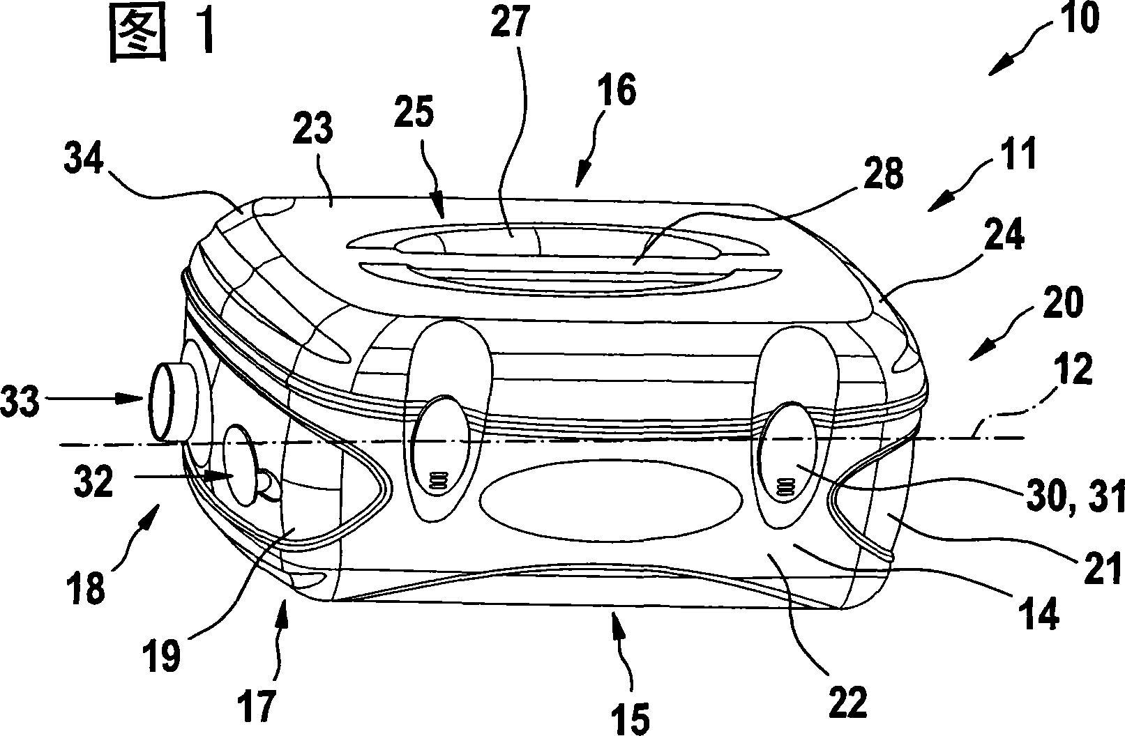
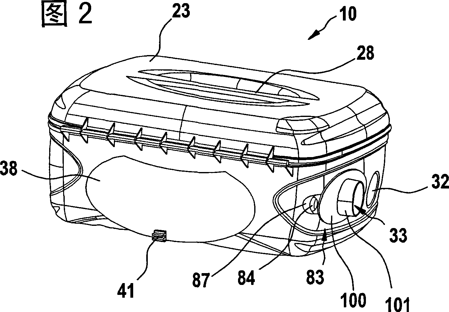
[0043] The longitudinal axis 12 of a box-type power source 10 shown in FIG. 1 , viewed obliquely from the front, can be seen in a perspective view, which extends parallel to the front side 14 and the rear side 16 . The lower region of the power source 10 is a six-sided, rectangular box 13 open at the top, which is closed on its underside 15 by means of a bottom 17 . Furthermore, the box 13 has a left side and a right side 18 , 20 as well as an upper side 25 which is represented by a cover 24 .

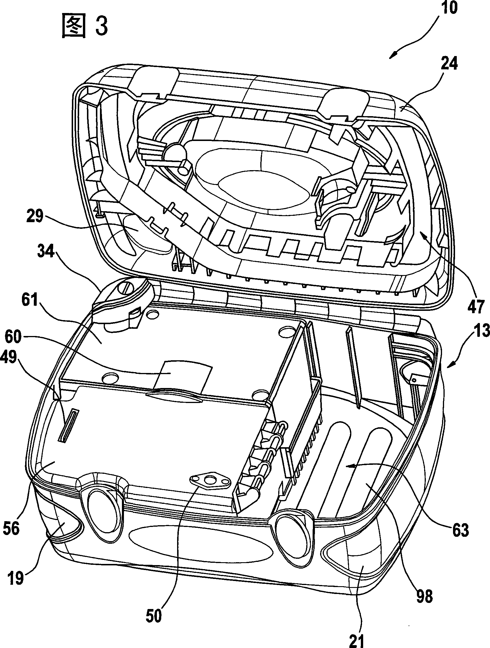
[0044] The case 13 consists of a case frame 22 in the form of a chassis made of impact-resistant, high-grade material, which carries a left and right side shell 19, 21 made of a relatively resilient, light material and said movable A pivotally mounted cover 24 fastened to the hinge side 25 forms the upper side 26 of the power source 10 .

[0045]The cover 24 consists of a cover frame 26 which, like the box frame 22 , is made of an impact-resistant high-grade material, on which—viewed ...


PUM


Abstract

An ancillary device for positioning a bone graft between bones separated by an articular slot, to ensure arthrodesis of a joint, wherein the bone graft is placed in a recess provided at the end of one or more bones defining the articular slot, and comprising means for driving the bone graft, provided with support means on the bone graft suitable for moving the latter in the recess, and actuation means, functionally connected to the driving means, and capable of being handled in order to control the movement of the bone graft.

Description

technical field [0001] The invention relates to a mobile power source for a hand-held power tool driven with suction and / or exhaust air. Background technique [0002] According to US 2003 / 0208874 A1 and EP 1 383 285 A2 compact workshop vacuum cleaners are known which are used as cleaning tools and which are provided with accessories for suctioning dust, chips etc. pattern work. Furthermore, WO 03 / 026841 A1 discloses a tool case which comprises a dust extraction unit for receiving chips and dust. These known vacuum cleaners or tool cases can only be used conditionally as a power source and as a transport case for hand-held power tools driven by suction or exhaust air. Contents of the invention [0003] The invention having the features of claim 1 results in a compact mobile power source which can be used both as a vacuum cleaner and for driving a machine tool, in particular a hand-held machine tool, which operates with an air flow, in the These power tools can be simulta...

Claims


Application Information

Patent Timeline
IPC IPC(8): B25H3/00A47L9/00
CPCB25H3/006A47L9/0009A47L9/0036A47L9/242A47L9/0027
Inventor S·蒂德J·埃斯F·富克斯
Owner ROBERT BOSCH GMBH
Why Eureka
Try Eureka