
Weft knitting machine

A technology of flat knitting machine and needle bed, applied in the field of flat knitting machine

Active Publication Date: 2007-11-14
SHIMA SEIKI MFG LTD
View PDF5 Cites 5 Cited by
  • Summary
  • Abstract
  • Description
  • Claims
  • Application Information

AI Technical Summary

Problems solved by technology

In such a state, it is impossible to provide sufficient support towards the side for the knitting needles holding the stitches

Method used


Image

  • Weft knitting machine
  • Weft knitting machine
  • Weft knitting machine

Examples


Embodiment Construction

[0024] Preferred embodiments applicable to the present invention will be described in detail with reference to the following drawings.

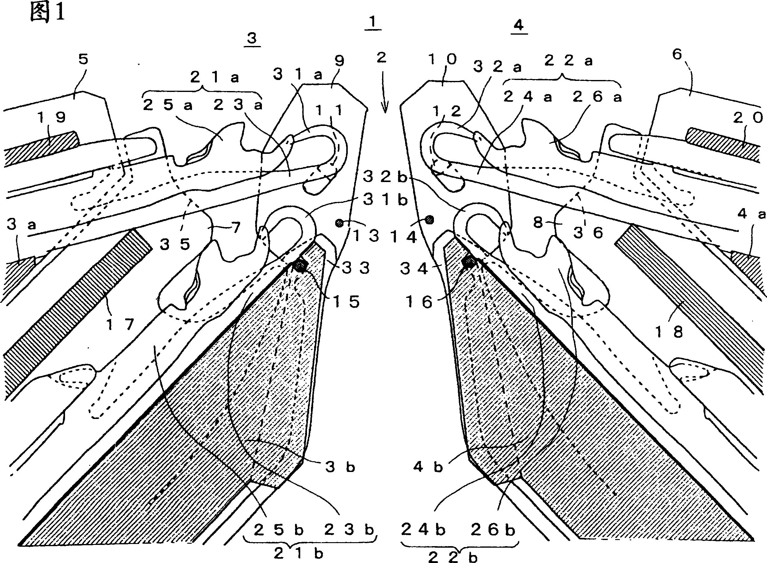
[0025] FIG. 1 shows a schematic configuration of a four-needle-bed flat knitting machine 1 as an embodiment of the present invention in a cross section near the needle bed 2. As shown in FIG. In the four-needle-bed flat knitting machine 1, the front needle beds 3 and the rear needle beds 4 facing each other across the needle bed 2 have upper needle beds 3a, 4a and lower needle beds 3b, 4b, respectively. In addition, in the following description, the front side is shown by the odd-numbered serial number, and the rear side is shown by the even-numbered serial number about the structural part which is paired front and back across the tooth gap 2. As shown in FIG. For components that are the same up and down, a is added to the upper layer side and b is added to the lower layer side, but a and b may be omitted when collectively referring to them. ...


PUM


Abstract

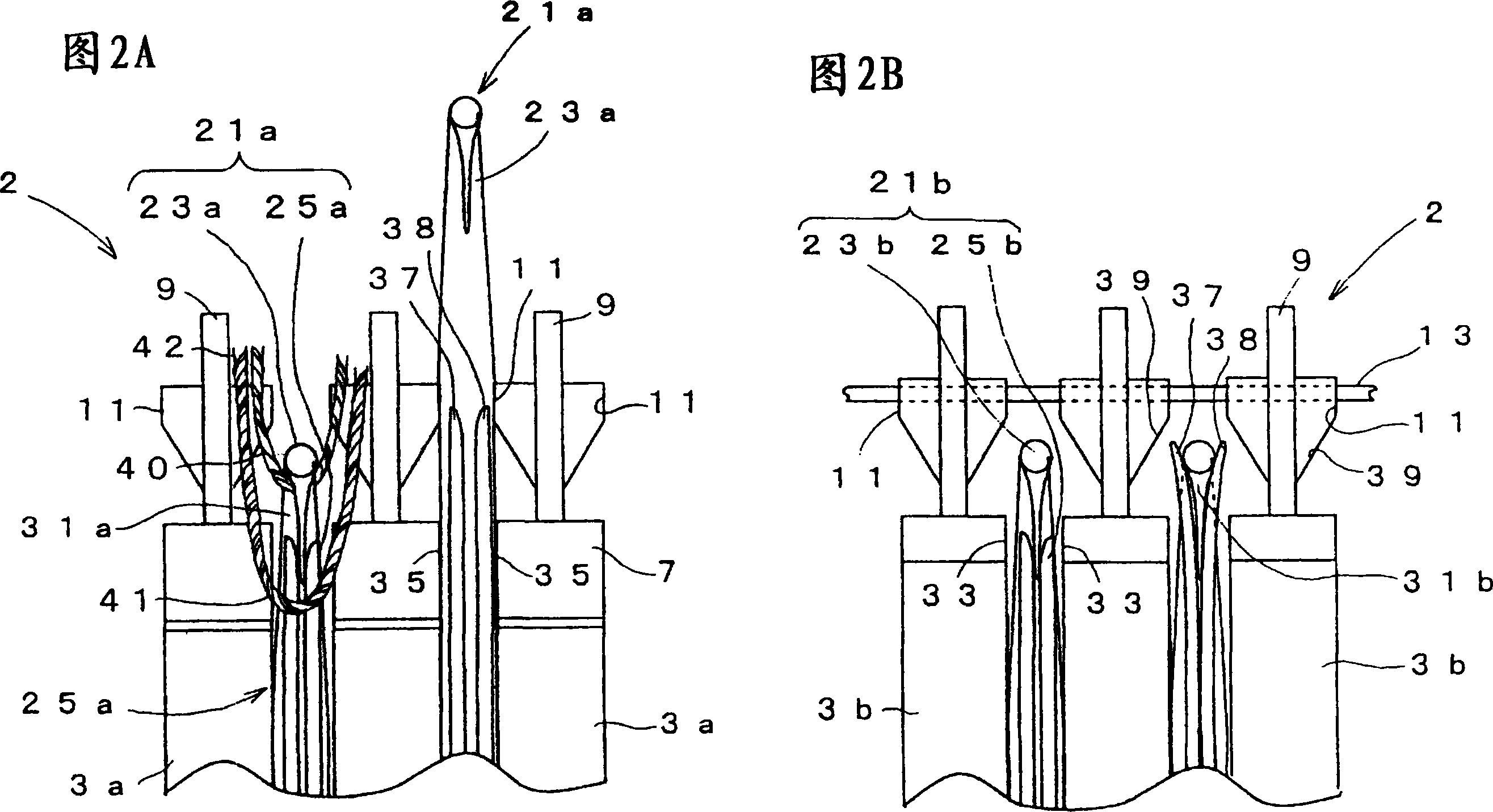
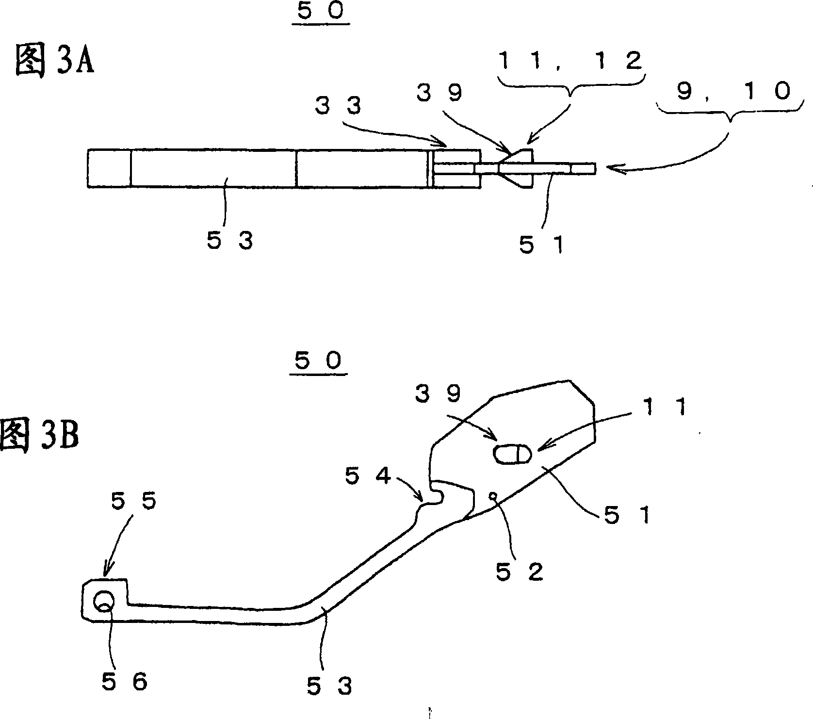
A weft knitting machine capable of supporting the knitting needles of needle beds against sufficient side loads even if multiple stages of needle beds are formed on the same side of a trick gap space. Fixed sinkers (9) and (10) are mounted at the tips of lower stage needle beds (3b) and (4b) and knitting needle supporting projections (11) and (12) are formed on the fixed sinkers (9) and (10) so that needle bodies (23a) and (24a) advancing from upper stage needle beds (3a) and (4a) to the trick gap space (2) can be supported from the side. The knitting needle supporting projections (11) and (12) are formed at positions where they are not interfered with the operation of the compound needles (21b) and (22b) of the lower stage needle beds (3b) and (4b). Thus, even if the needle bodies (23a) and (24a) of the upper stage needle beds (3a) and (4a) receive a load to the side, the large bending thereof can be suppressed by the contact thereof with the knitting needle supporting projections (11) and (12) and sufficient side support can be performed for the needle bodies.

Description

technical field [0001] The present invention relates to a four-needle-bed flat knitting machine, in which at least one of the front needle beds and the rear needle beds facing each other across needle beds has two layers of needle beds. Background technique [0002] In the prior art, a flat knitting machine performs a knitting operation in which a plurality of knitting needles arranged in parallel on a needle bed advance and retreat relative to the needle bed, and knits a knitted fabric while drawing in the knitting yarn supplied from the needle bed to form loop loops. . Parallel needle grooves are formed on the needle bed, and the knitting action of the knitting needles is guided by the needle grooves. The knitting needle slides and displaces in the direction of advancing and retreating relative to the needle bed in the needle groove, and is supported by the side surface of the needle groove in the direction perpendicular to this direction. However, the ends of the knitti...

Claims


Application Information

Patent Timeline
Patent Type & Authority Applications(China)
IPC IPC(8): D04B15/06
CPCD04B7/00D04B15/10D04B15/06D04B35/06
Inventor 中森岁德
Owner SHIMA SEIKI MFG LTD
Learn More