Thermodynamic expansion valve

A thermal expansion valve and valve body technology, applied in the field of expansion valves, can solve the problems that the temperature sensing bulb cannot be controlled correctly, and it is difficult to realize product miniaturization, etc., and achieve the effect of simple and reliable sealing, simple sealing operation, and increased degree of freedom

Active Publication Date: 2007-11-21
ZHEJIANG SANHUA AUTOMOTIVE COMPONENTS CO LTD
View PDF1 Cites 10 Cited by
  • Summary
  • Abstract
  • Description
  • Claims
  • Application Information

AI Technical Summary

Problems solved by technology

[0009] The technical problem to be solved and the technical task proposed by the present invention are to overcome the defects of the existing technology that it is difficult to realize pro...

Method used


Image

  • Thermodynamic expansion valve
  • Thermodynamic expansion valve
  • Thermodynamic expansion valve

Examples


Embodiment Construction

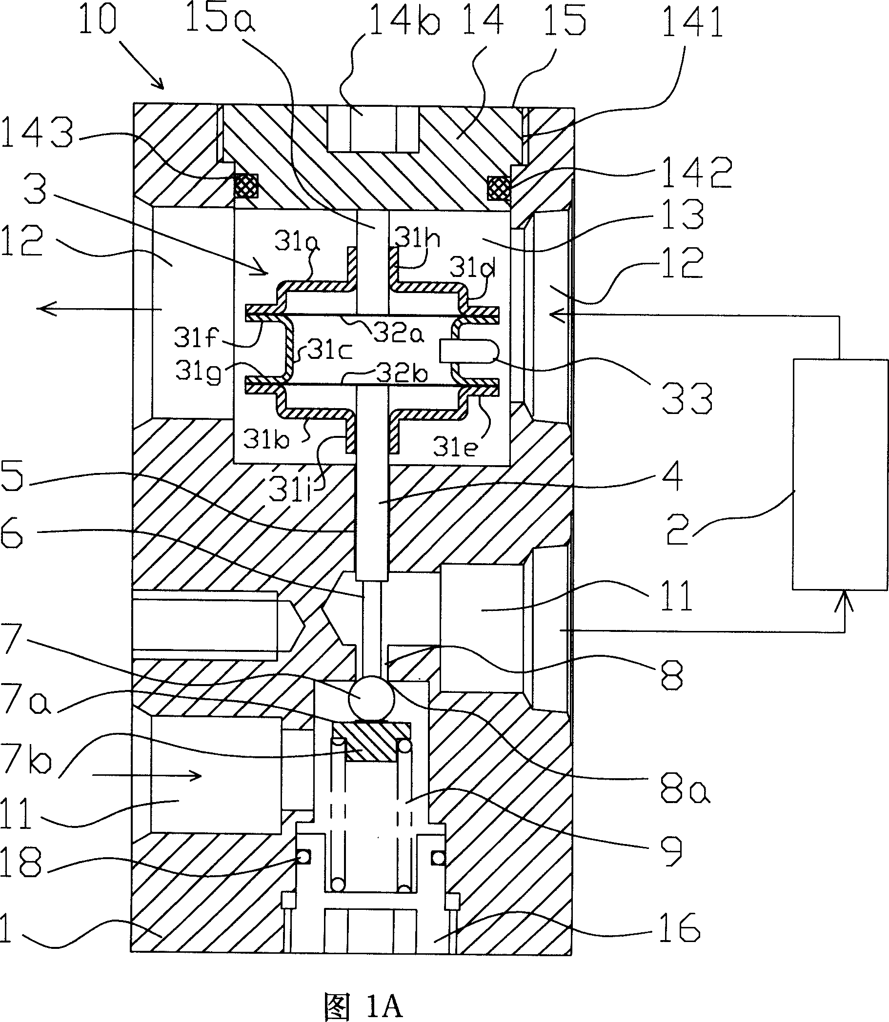
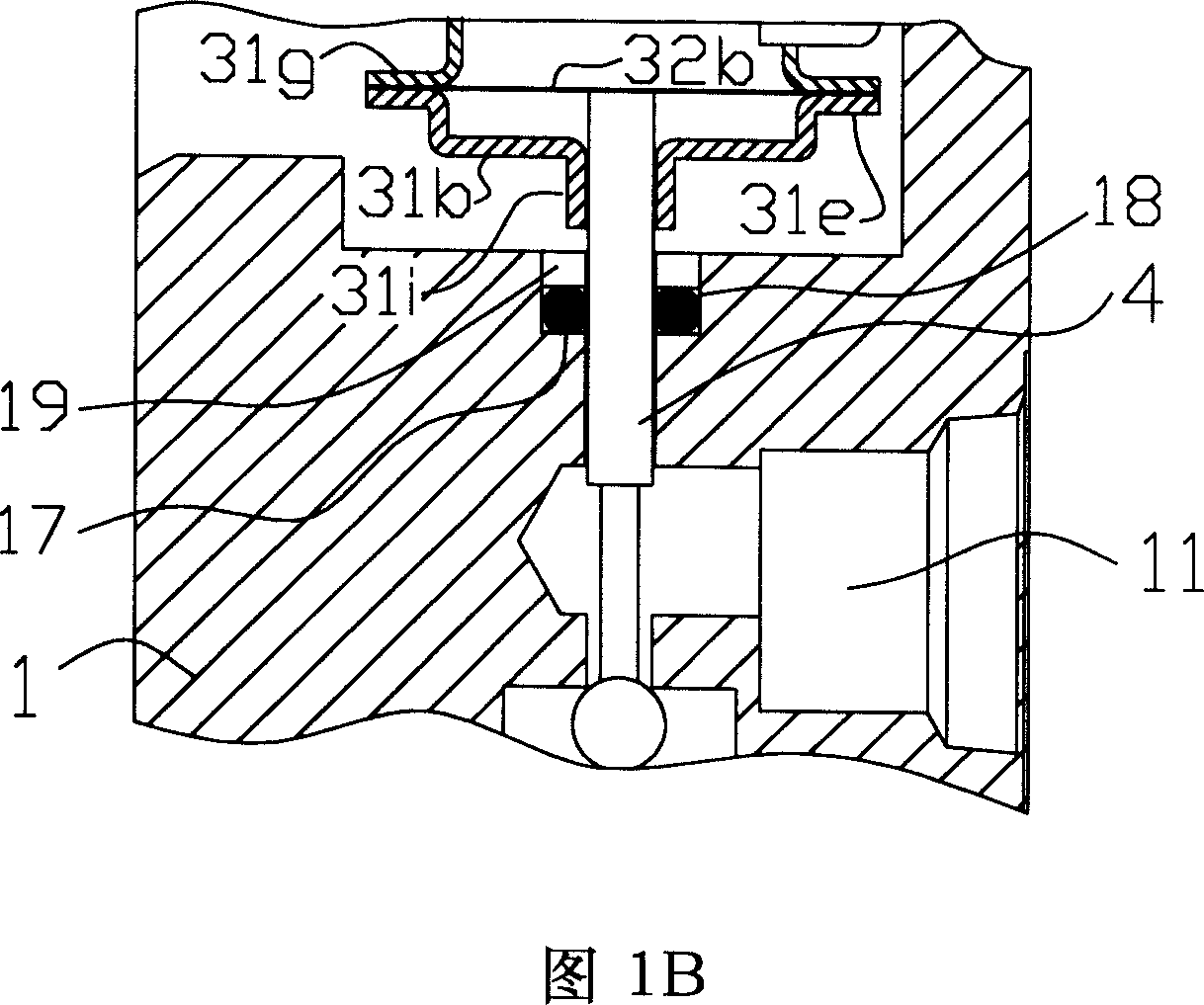
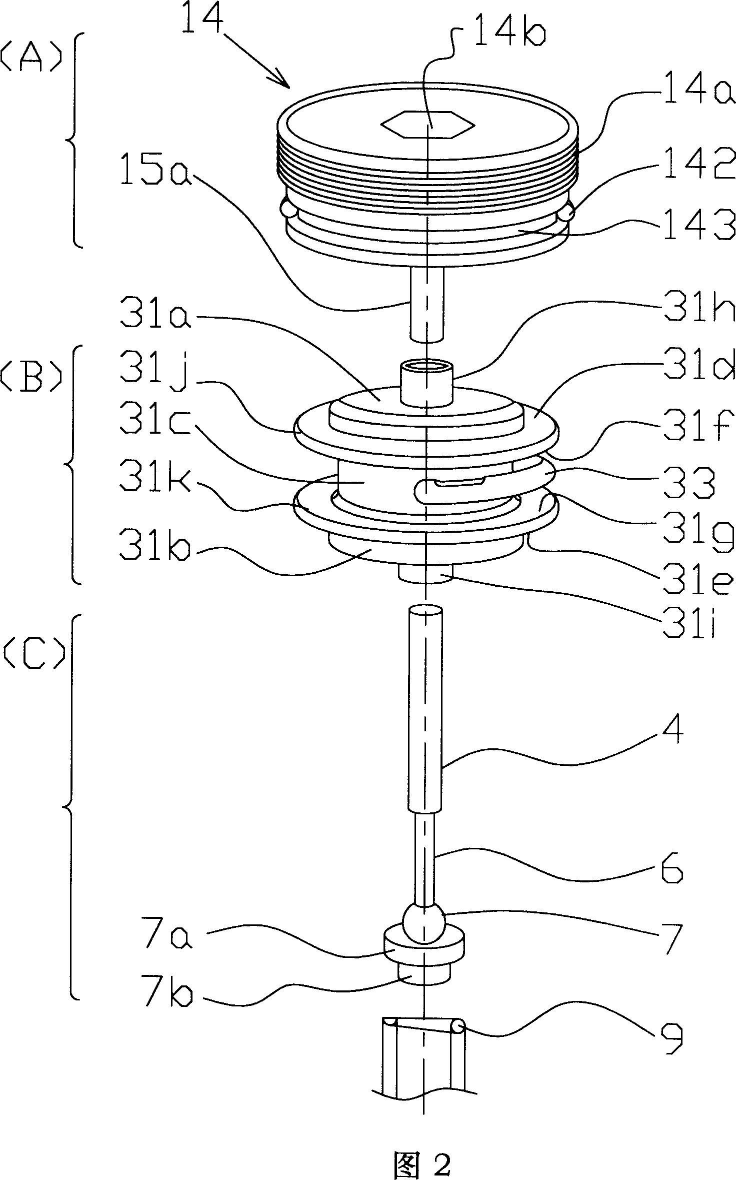
[0040] FIG. 1A is a longitudinal sectional view of a thermal expansion valve 10 according to an embodiment of the present invention. This thermal expansion valve is used in a refrigerating cycle of an automobile air conditioner and the like like conventional expansion valves.

[0041] In the figure, a prismatic valve body 1 made of metal such as aluminum is formed, and the high-pressure refrigerant discharged from the compressor (not shown) flows into the high-pressure passage 11 of the evaporator 2 and the low-pressure refrigerant discharged from the outlet of the evaporator 2 flows into the evaporator. The low-pressure passage 12 of the compressor, the high-pressure passage 11 and the low-pressure passage 12 are parallel to each other. On the way from the outlet of the evaporator 2 into the low-pressure passage 12 of the compressor, an insertion portion 13 for inserting the temperature-sensing package 3 is provided, and an insertion hole 15 larger than the temperature-sensing...


PUM


Abstract

A kind of heating-power bulgy valve, including: the body of the valve, on the body of the valve, there are the high voltage passageway, the low voltage passageway and the valve port for the high voltage passageway; the spool, it is close to and pressed to the valve port by a spring; temperature package, it has a airtight room what is composed by membrane; The valve handle, one of its ends poling the spool away from the valve port, another end is droved by membrane; the character is that the temperature package locates on the low voltage passageway. Because of that, it compares to the existing technical, can make the heating-power bulgy valve smaller, so it can insure the special freedom in the refrigerant cycle.

Description

technical field [0001] The present invention relates to an expansion valve for controlling the flow rate of refrigerant sent to an evaporator in refrigerating cycles such as air conditioners and refrigerating devices. Background technique [0002] Existing expansion valves are generally formed on the valve body with a high-pressure passage for passing high-pressure refrigerant to the evaporator and a low-pressure passage for sending low-pressure refrigerant from the evaporator, and a valve port on the high-pressure passage. The valve core is spring-pressed toward the valve port, and the valve body is fixed with a temperature-sensing package that senses the temperature and pressure changes of the low-pressure refrigerant. The valve stem is supported between the diaphragm and the valve core. When the low-pressure refrigerant When the temperature and pressure change, the diaphragm action of the temperature sensing package drives the valve stem to change ...

Claims


Application Information

Patent Timeline
IPC IPC(8): F16K1/14F16K31/68F25B41/06
CPCF25B2341/0683
Inventor 小池隆志史初良尹斌
Owner ZHEJIANG SANHUA AUTOMOTIVE COMPONENTS CO LTD
Why Eureka
Try Eureka