
Detector array and its apparatus

A detector array and detector technology, which is applied in the field of detectors, can solve the problem of insoluble object edge recognition, affecting the correct rate of material recognition, false recognition results, etc.

Active Publication Date: 2007-11-21
TSINGHUA UNIV +1
View PDF5 Cites 12 Cited by
  • Summary
  • Abstract
  • Description
  • Claims
  • Application Information

AI Technical Summary

Problems solved by technology

However, there is a serious defect when this alternate generation of high and low-energy X-rays scans objects: two kinds of X-rays with different energies are alternately generated at a certain frequency, and there is a certain time interval between the two beams.
Therefore, this will affect the accuracy of material identification, especially at the edge of the object to be inspected, there is a phenomenon that the rays of two energies interact with different objects, thus obtaining wrong identification results
At the same time, in order to reduce the error caused by the interaction between high and low energy rays and non-identical substances, the traditional method is to make the object to be inspected move slowly, which will seriously limit the efficiency of cargo inspection
Moreover, the problem of false recognition of the edge of the object still cannot be solved

Method used


Image

  • Detector array and its apparatus
  • Detector array and its apparatus
  • Detector array and its apparatus

Examples


Embodiment Construction

[0023] Specific embodiments of the present invention will be described in detail below with reference to the accompanying drawings.

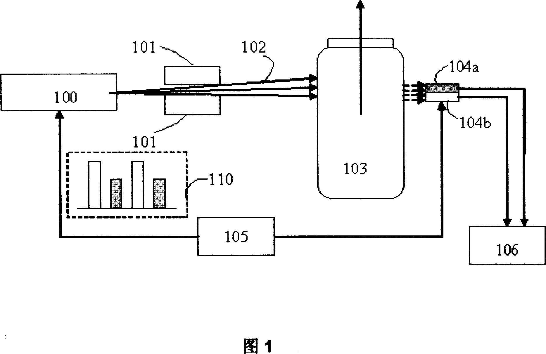
[0024] Fig. 1 is a schematic diagram of a system for realizing material identification by using a dual-column detector array according to an embodiment of the present invention.

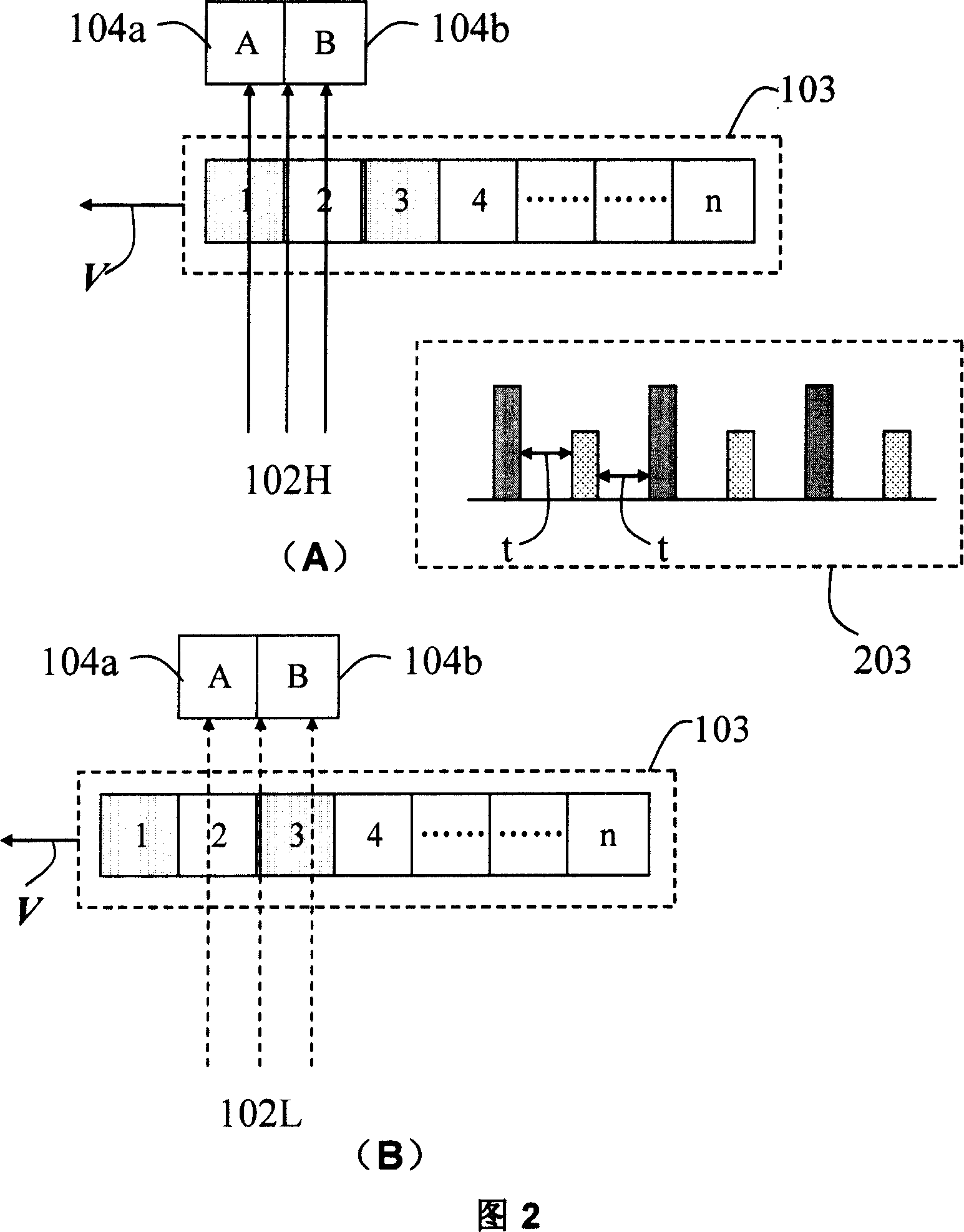
[0025] As shown in FIG. 1 , a detector array including a first linear array detector 104 a and a second linear array detector 104 b is used to collect dual-energy rays alternately generated by a radiation source. The radiation source 100 is capable of alternately generating radiation such as X-rays. The synchronization control part 105 provides a synchronization signal 110 to the radiation source 100 and the first line detector 104a and the second line detector 104b, so that the timing of the synchronization signal 110 of the radiation source 100 alternately generates high and low energy radiation.

[0026] The radiation 102 generated by the radiation source 100 passe...


PUM


Abstract

A detector array consists of the first linear-array detector used to detect the first ray penetrating at least part of detected object, the second linear-array detector set in parallel to the first one and used to detect the second ray being emitted alternatively to the first one and being used to penetrate at least part of detected object.

Description

technical field [0001] The present invention relates to a detector for radiographic imaging of an object, in particular to a detector array and a device using the detector array, so as to eliminate damage to the object material at the edge that occurs during the inspection of the inspected object by alternately generated rays. Error identification and identification inaccurate problems, and can double the efficiency of scanning inspection. technical background [0002] With the continuous improvement of customs and security inspection system requirements, the technology of using two kinds of X-rays with different energies to carry out non-destructive inspection on the inspected object and realize the identification of the material and material of the inspected object has begun to be widely promoted, such as the United States patent US 5,044,002. Recently, in the non-destructive testing of large objects, the technology of realizing material identification by dual-energy meth...

Claims


Application Information

Patent Timeline
Patent Type & Authority Applications(China)
IPC IPC(8): G01N23/04G01N23/083
CPCG01N23/087A61B6/482G01N2223/5015G01V5/0041G01V5/224G01N23/083G01V5/20
Inventor 王学武陈志强李元景钟华强张清军赵书清
Owner TSINGHUA UNIV
Learn More