Vehicle seat

一种座椅、车辆的技术,应用在车辆座椅、活动座椅、车辆部件等方向,能够解决繁琐管理等问题,达到抑制冲击载荷的减小、抑制姿势错乱的效果

Inactive Publication Date: 2007-11-28
HONDA MOTOR CO LTD +1
View PDF1 Cites 4 Cited by
  • Summary
  • Abstract
  • Description
  • Claims
  • Application Information

AI Technical Summary

Problems solved by technology

Therefore, in order to stabilize the fracture caused by the impact load, cumbersome management in manufacturing is required.

Method used


Image

  • Vehicle seat
  • Vehicle seat
  • Vehicle seat

Examples


Embodiment Construction

[0050] Hereinafter, the best mode for carrying out the present invention will be described with reference to the drawings. "Front", "rear", "upper", "lower", "left", and "right" in the figure represent the directions seen from the occupant seated in each vehicle seat, respectively. Moreover, the drawings are viewed according to the orientation of the reference numerals.

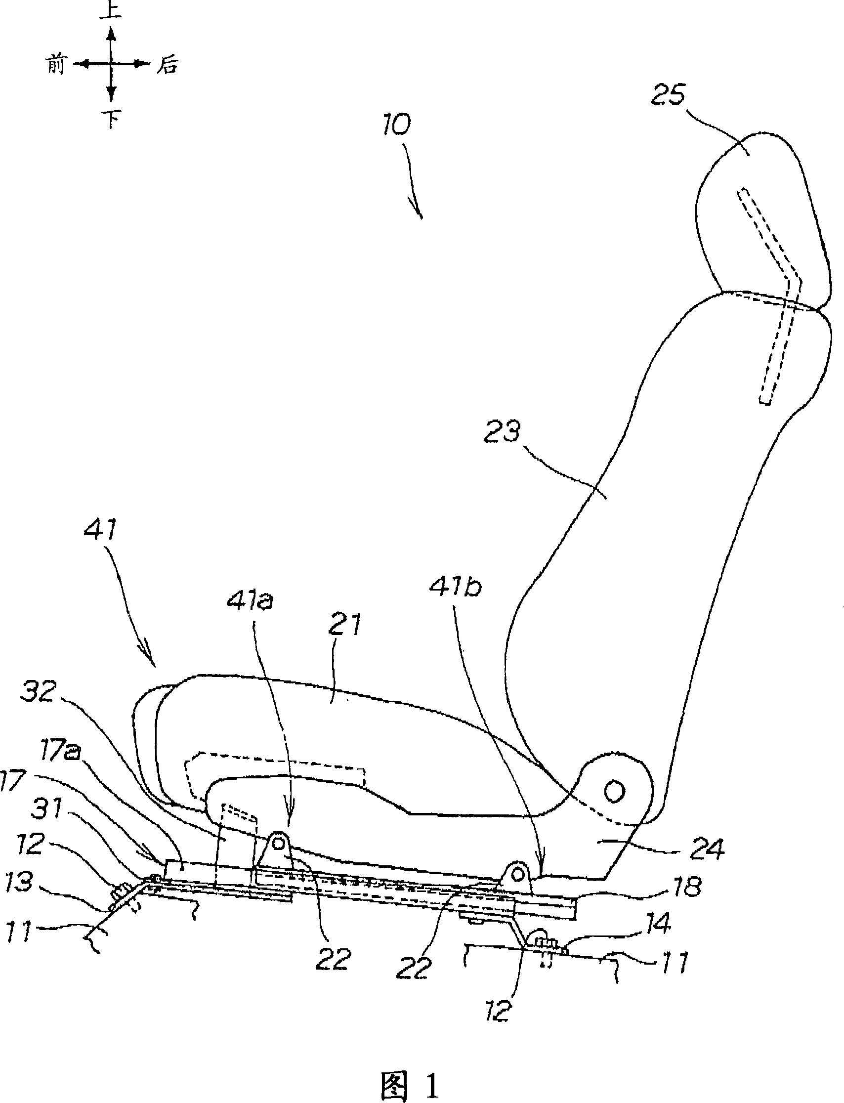
[0051]Fig. 1 is a side view of the vehicle seat of the present invention. The basic structure of the vehicle seat 10 includes: a front seat bracket 13 and a rear seat bracket 14 mounted on the side of the vehicle body 11 through fastening members 12 and 12. the guide rail 17 installed on these front seat brackets 13 and the rear seat bracket 14; the slider 18 engaged with the guide rail 17 and slidably provided; the front and rear parts installed on the slider 18 holding brackets 22, 22; plate-shaped side brackets 24 supported on these holding brackets 22, 22; headrest.

[0052] The impact absorbing plate ...


PUM


Abstract

The purposes of the invention is to provide a vehicle seat easily and stably making control of impact load. In an impact absorption plate 31, a breaking generation part 44 to be broken by impact is arranged between a front part 31z of the impact absorption plate 31 and a vehicle body 11 side so as to extend to a front / rear sides of the vehicle, and the impact absorption plate 31 is fixed to a front part 13a and a rear part 13b of a front seat bracket 13 provided at the vehicle body side through rivets 33, 33. A part of the front part 31z of the impact absorption plate 31 is cut to form a cut part 45, and a front end 17a of a rail 17 provided on a seat sitting part side is mounted to a projection part 35 molded so as to upwardly swell an inner side portion of the cut part 45 through a rivet 34.

Description

technical field [0001] The present invention relates to a vehicle seat having a shock-absorbing panel that breaks when a force of a certain magnitude or more is applied to absorb the shock. Background technique [0002] Conventionally, a vehicle seat has been disclosed that has a shock absorbing plate that breaks when a force of a certain magnitude or more is applied to absorb the impact, and that the seat portion is connected to the vehicle body side through the shock absorbing plate. (For example, refer to Patent Document 1). [0003] Patent Document 1: Japanese Patent Application Laid-Open No. 2001-260726 (FIG. 5). [0004] Patent Document 1 is explained based on the following drawings. [0005] FIG. 13 is an explanatory diagram of a basic configuration of the prior art, showing one of seat frames arranged between the vehicle body side and the vehicle seat to support the left and right sides of the vehicle seat. [0006] The seat frame 100 includes: a seat bracket 101 ...

Claims


Application Information

Patent Timeline
Patent Type & Authority Applications(China)
IPC IPC(8): B60N2/42
CPCB60N2/015B60N2/42736B60N2/42709B60N2/06B60N2/4228
Inventor 栗田真宇野晃二蛭田行男森田嘉明植田胜增田诚克鬼头英幸
Owner HONDA MOTOR CO LTD
Why Eureka
Try Eureka