
Coil framework and electromagnetic coil

A coil bobbin and electromagnetic coil technology, applied in the direction of electromagnets, transformer/inductor cores, valve details, etc., can solve problems such as placement and fixing without consideration, achieve reliable connection, improve position retention, and configure Simple operation effect

Active Publication Date: 2011-02-16
ZHEJIANG SANHUA INTELLIGENT CONTROLS CO LTD
View PDF1 Cites 1 Cited by
  • Summary
  • Abstract
  • Description
  • Claims
  • Application Information

AI Technical Summary

Problems solved by technology

[0006] Moreover, the technical solution of Patent Document 1 is used on the electromagnetic coil, without considering the placement and fixing of the electrical components connected to the winding and lead wires on the electromagnetic coil

Method used


Image

  • Coil framework and electromagnetic coil
  • Coil framework and electromagnetic coil
  • Coil framework and electromagnetic coil

Examples


Embodiment Construction

[0048] Embodiments of the present invention are described below with reference to the drawings.

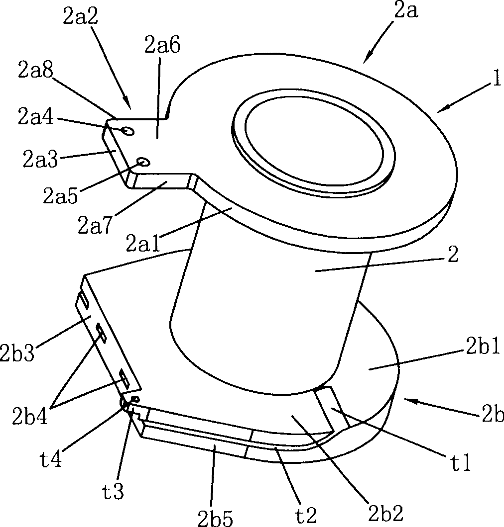
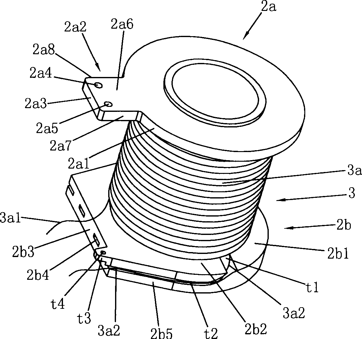
[0049] figure 1 It is a perspective view of the bobbin 1 of the electromagnetic coil concerning embodiment of this invention.

[0050] The bobbin 1 is composed of a winding core 2 and a first flange-shaped portion 2a and a second flange-shaped portion 2b fixed at both ends of the winding core 2 in parallel.

[0051] The winding core 2 is in the shape of a hollow circular tube, and the winding core 2 and the two flange parts are integrally formed by synthetic resin, such as injection molding, and the resin material is such as polybutylene terephthalate.

[0052] In the framework 1, the first flange-like portion 2a is hollow and approximately disc-shaped, and has an outer peripheral surface 2a1, and a protruding plate-shaped approximately square plate-shaped portion 2a2 is provided on the outer peripheral surface 2a1, and the plate-shaped portion 2a2 has a front end surface. 2a3, ...


PUM


Abstract

The invention discloses a magnet coil, which comprises the following parts: a magnet coil skeleton comprised by the core and the parallel first cultellus portion and second cultellus portion at two sides of the core, a winding coiled on the core, a lead wire connected with the winding and a synthetic resin encapsulated layer encapsulated at the peripheric of the winding. The invention changes thecoil skeleton: the evagination edge of the first cultellus portion is equipped with the approximate square plate-like element, the plate-like element is equipped with electric element, the second cultellus portion is equipped with trench-like dent, and the lead wire of the coin is arranged at the trench-like dent. The invention can avoid the shift of the element and the lead wire or the position deviation owing to the shift, which makes the electric element, the lead wire and the coil exist an insulated distant and avoids the generation of the imperfect.

Description

technical field [0001] The present invention relates to an electromagnetic coil used for a control valve and a coil frame constituting the electromagnetic coil, especially related to the placement of the electromagnetic coil and the electrical components used therein, as well as the packaged electromagnetic coil such as winding wires and lead wires. Background technique [0002] Electromagnetic control valves, electromagnetic solenoids for refrigeration cycles, or electromagnetic coils for four-way switching valves for refrigeration cycles are used to convert electric power into magnetic force to change the working state of the valve, and the change of the working state of the valve may be the limit position Changes, such as the opening or closing of the medium circulation pipeline, may also be the degree of maintenance of a working state, such as the size of the opening of the medium circulation pipeline. [0003] This kind of electromagnetic coil generally consists of a ho...

Claims


Application Information

Patent Timeline
Patent Type & Authority Patents(China)
IPC IPC(8): H01F7/06H01F27/24F16K31/06
Inventor 张胜昌胡梅宴张磊
Owner ZHEJIANG SANHUA INTELLIGENT CONTROLS CO LTD
Learn More