Housing of an electrical machine comprising cooling channels extending in a housing wall

A technology for cooling channels and shell walls, applied in cooling/ventilation devices, casings/covers/supports, electromechanical devices, etc., can solve problems such as high production costs and unsatisfactory results, and achieve sealing, Simple diversion function, cost reduction effect

Inactive Publication Date: 2007-11-28
SIEMENS AG
View PDF0 Cites 14 Cited by
  • Summary
  • Abstract
  • Description
  • Claims
  • Application Information

AI Technical Summary

Problems solved by technology

This form of sealing requires high production costs and sometimes does not lead to satisfactory results

Method used


Image

  • Housing of an electrical machine comprising cooling channels extending in a housing wall
  • Housing of an electrical machine comprising cooling channels extending in a housing wall
  • Housing of an electrical machine comprising cooling channels extending in a housing wall

Examples


Embodiment Construction

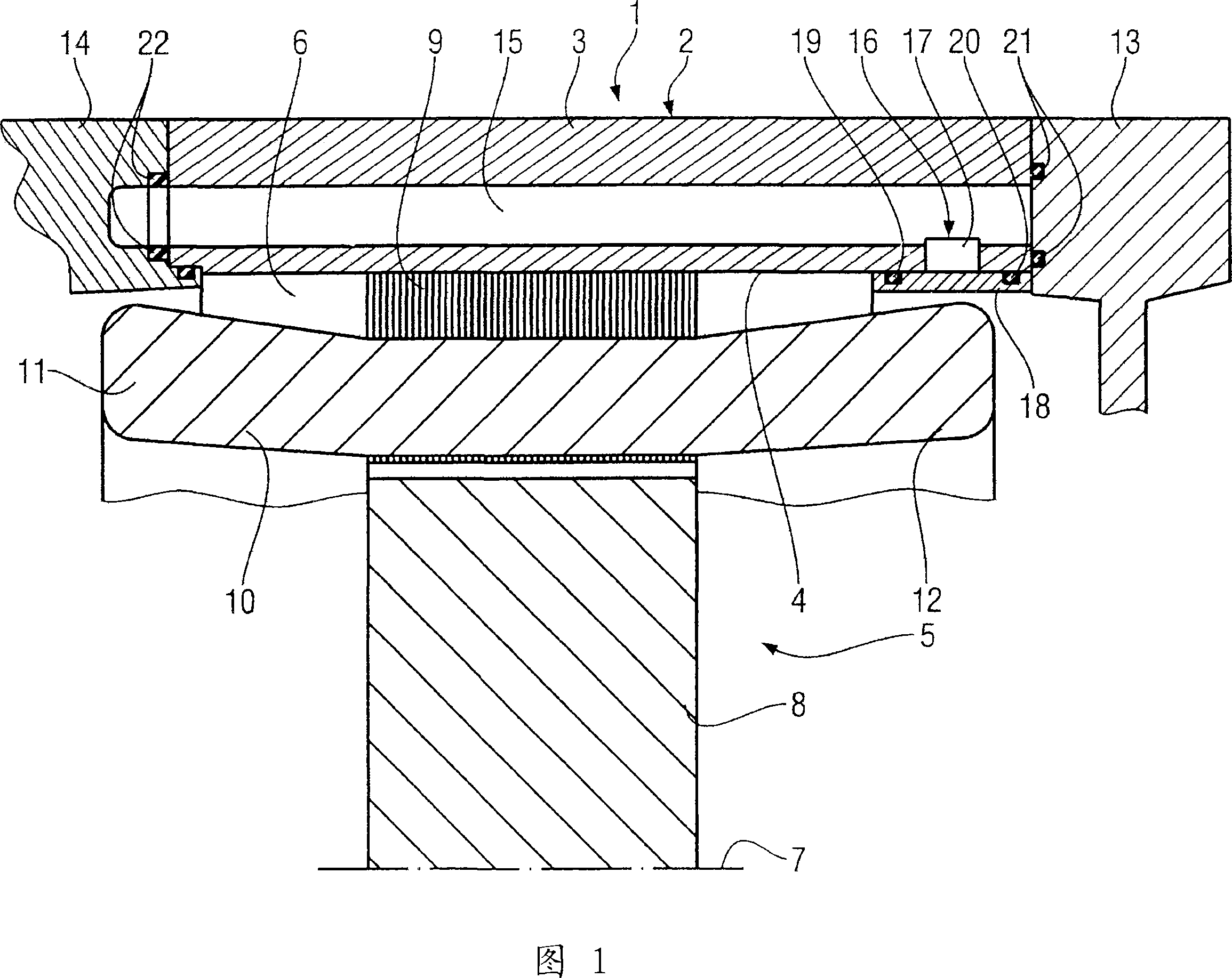
[0025] FIG. 1 shows a cross-section of an electric machine 1 in the form of an electric motor with a first embodiment of a housing 2 . The housing 2 , which is designed as an extruded part, has a housing 3 with an inner surface 4 surrounding a hollow cylindrical interior 5 . Inside the hollow interior 5 , a stator 6 , which is reliably fixed in the housing 2 , and a rotor 8 , which is rotatably supported around a rotation axis 7 , are arranged. The stator 6 comprises a stator lamination 9 , in which the electrical conductors of a winding system 10 run. In the axial direction, ie in the direction of the axis of rotation 7 , the winding system 10 has a winding tap 11 and 12 in each case facing the stator lamination 9 on both sides. The housing 2 is open on both sides in the axial direction. On this open side, a bearing cap 13 and 14 are respectively provided as connections.

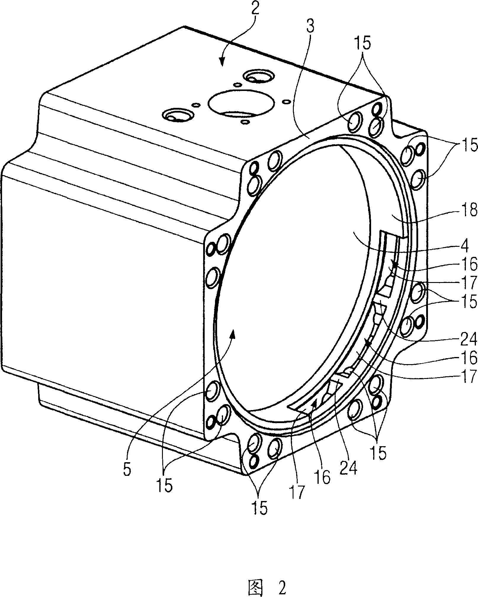
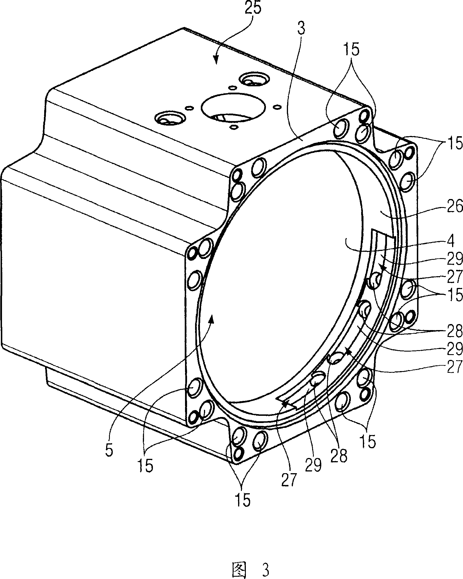
[0026] The housing 2 comprises a plurality of cooling channels 15, only one of which is shown in the ...


PUM


Abstract

The invention relates to an electrical machine housing with cooling channels extending towder the inner housing. The housing (2) for an electrical machine (1), said housing comprising a housing wall (3) having an inner surface (4). At least two cooling channels (15) extend inside the housing wall. A connecting deviation channel (16) is provided between two of the cooling channels (15). The inventive housing is also provided with an inner sealing ring (18) applied to the inner surface (4). The housing wall (3) comprises at least one housing recess (17) on the inner surface (4) thereof, in the region of the inner sealing ring (18), such that, together with the inner sealing ring (18), it forms the deviation channel (16).

Description

technical field [0001] The invention relates to an electric machine housing with a housing wall having an inner surface and at least two cooling channels extending in the housing wall of the electric machine. Background technique [0002] Such a housing, in particular fluid-cooled by the electric machine, is used, for example, as an extruded component. The electrical machine can be designed as an electric motor or as a generator. The cooling channel extends approximately in the axial direction, ie in the direction of the axis of rotation of a rotor mounted rotatably within the housing. At both ends of the housing, the cooling fluid guided in the cooling channel during operation is guided in the bearing shield in the intermediate flange or by means of the baffles. In this case, cast or subsequently drilled bore channels or ducts are used in the bearing shield or the intermediate flange, which is designed in particular as a cast part, to guide the cooling fluid in a flow-con...

Claims


Application Information

Patent Timeline
Patent Type & Authority Applications(China)
IPC IPC(8): H02K5/20
CPCH02K5/20H02K9/19H02K5/203
Inventor 马库斯·普拉滕塞巴斯蒂安·雷德迈克尔·齐斯勒
Owner SIEMENS AG
Why Eureka
Try Eureka