Corn strew grinding return-to-field machinery

A technology of corn stalks and racks, which is applied in the field of corn stalk crushing and returning machines, which can solve the problems of uneven scatter and affect the growth and development of wheat, and achieve the effect of even scatter scatter

Inactive Publication Date: 2007-12-05
SHANDONG UNIV OF TECH
View PDF0 Cites 12 Cited by
  • Summary
  • Abstract
  • Description
  • Claims
  • Application Information

AI Technical Summary

Problems solved by technology

Since the width of the straw returning machine is smaller than the width between the two driving wheels of the tractor, when the straw returning mach

Method used


Image

  • Corn strew grinding return-to-field machinery
  • Corn strew grinding return-to-field machinery

Examples


Example Embodiment

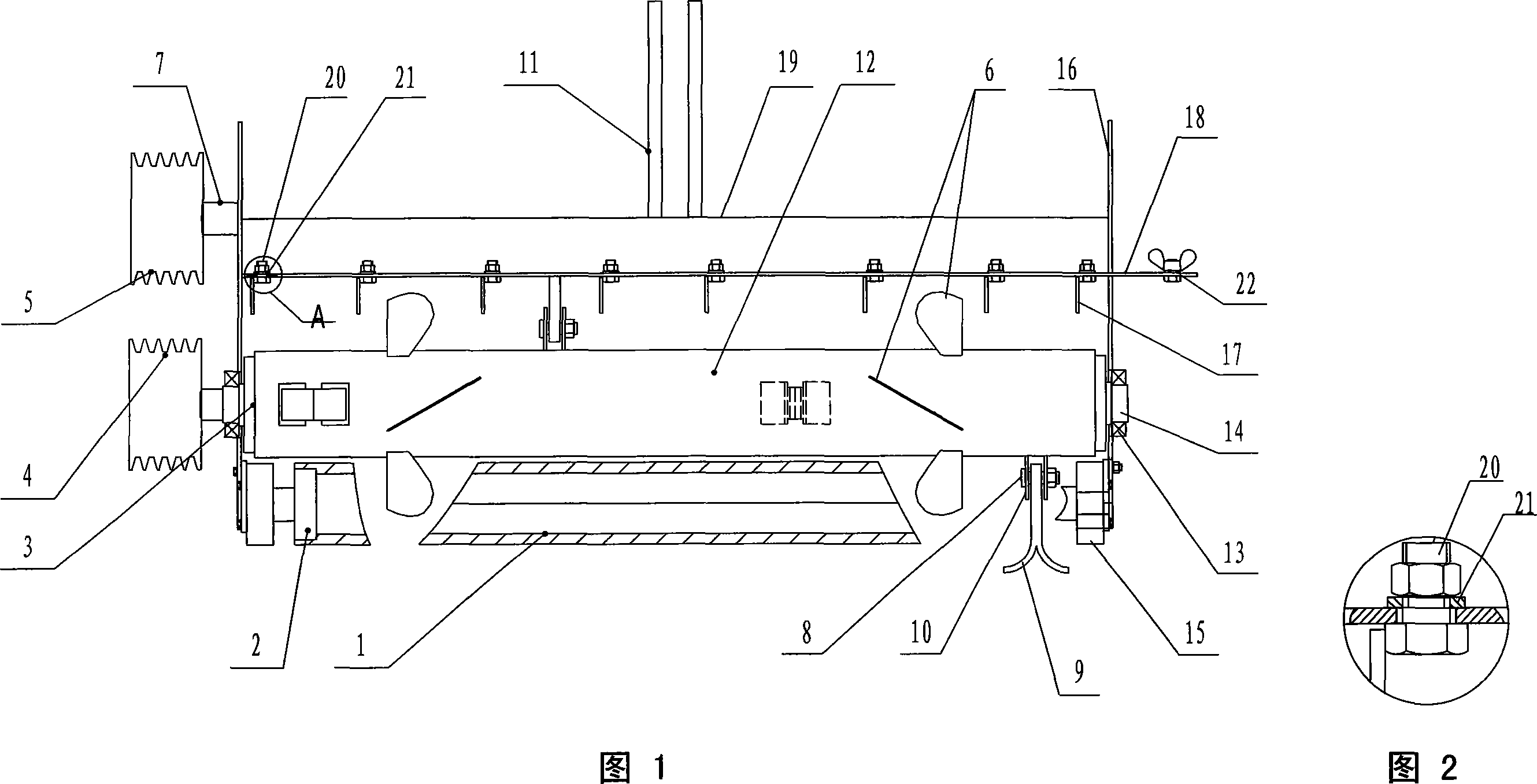
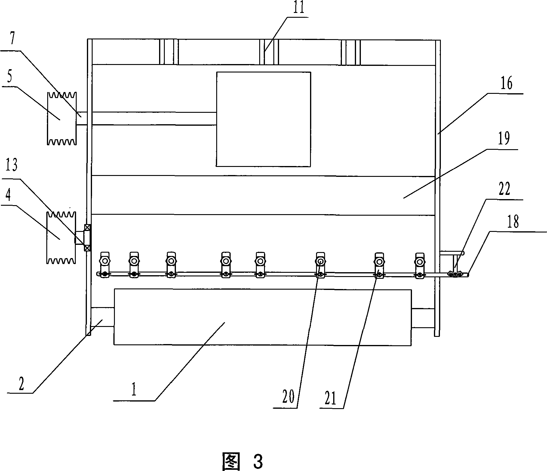
[0017] In the embodiment shown in Figures 1 to 3: both ends of the pressing wheel 1 are provided with shaft heads 2, which are installed on the rear lower part of the hood 19 through sliding bearings 15, and shaft heads 3 are correspondingly provided at both ends of the cutter shaft 12. And the shaft head 14, and is installed on the frame 16 through the rolling bearing 13, the passive pulley 4 is installed at the end of the shaft head 3, and the driving pulley 5 connected with its transmission is installed on the shaft end of the gearbox output shaft 7, fixed The four tool seats 10 with the Y-shaped throwing knife 9 are evenly distributed on the tool shaft 12 in the form of a single helix. There is a set of fan blades 6 between the knife bases 10, and the four fan blades 6 in each group are evenly distributed around the same circumference of the knife shaft 12 at an inclination angle of 15 degrees; The head of the hood is evenly movably installed on the inner side of the rear ...


PUM

PropertyMeasurementUnit
Inclinationaaaaaaaaaa

Abstract

The corn stalk crushing and throwing machine includes one frame, one spiral throwing cutter with one shaft mounted through rolling bearing onto the frame, one horizontal pressing wheel mounted through sliding bearing onto the frame, one hood and guide plates in the back part of the hood. It features the increased groups of blades mounted homogeneously onto the cutter shaft and the guide plates mounted through an angle regulating mechanism. During operation, the high speed rotating blades produce axial force to through the crushed stalk homogeneously in certain angle range.

Description

Technical field [0001] The invention provides a corn stalk crushing and returning machine with fan blades, which belongs to the technical field of agricultural machinery. Background technique [0002] At present, the general-purpose straw crushing and returning machines are mostly composed of a frame, a machine cover, a pressing wheel, a rotating knife shaft, a fixed knife seat, a throwing knife, and a deflector. The pressing wheel is installed on the rear lower part of the machine cover through sliding bearings; the rotating knife shaft is installed on the machine cover through rolling bearings, and the fixed knife seat is evenly welded on the knife shaft in a spiral line; the moving knife and the fixed knife seat are generally connected by bolts. The two sides of the hood are welded together with the frame, and a plurality of deflectors are welded on the rear inner side of the hood, and the direction is perpendicular to the hood and is the same as the forward direction of ...

Claims


Application Information

Patent Timeline
IPC IPC(8): A01D82/00A01F29/01
Inventor 李其昀
Owner SHANDONG UNIV OF TECH
Why Eureka
Try Eureka