Porcelain brick conveying robot unit

A technology for manipulators and ceramic tiles, applied in the directions of manipulators, chucks, manufacturing tools, etc., can solve the problems of lack of practical auxiliary tools, high handling costs and poor safety for ceramic tile handling, and achieve safe and fast handling, convenient use and simple structure. Effect

Inactive Publication Date: 2007-12-05
于复生
View PDF0 Cites 13 Cited by
  • Summary
  • Abstract
  • Description
  • Claims
  • Application Information

AI Technical Summary

Problems solved by technology

[0003] The purpose of the present invention is to solve the problems of lack of practical auxiliary tools for tile handling at present, resulting in high handling costs and poor safety, and to provide a tile handling manipulator device with simple structure, convenient use, and safe and fast handling of tiles

Method used


Image

  • Porcelain brick conveying robot unit

Examples


Embodiment Construction

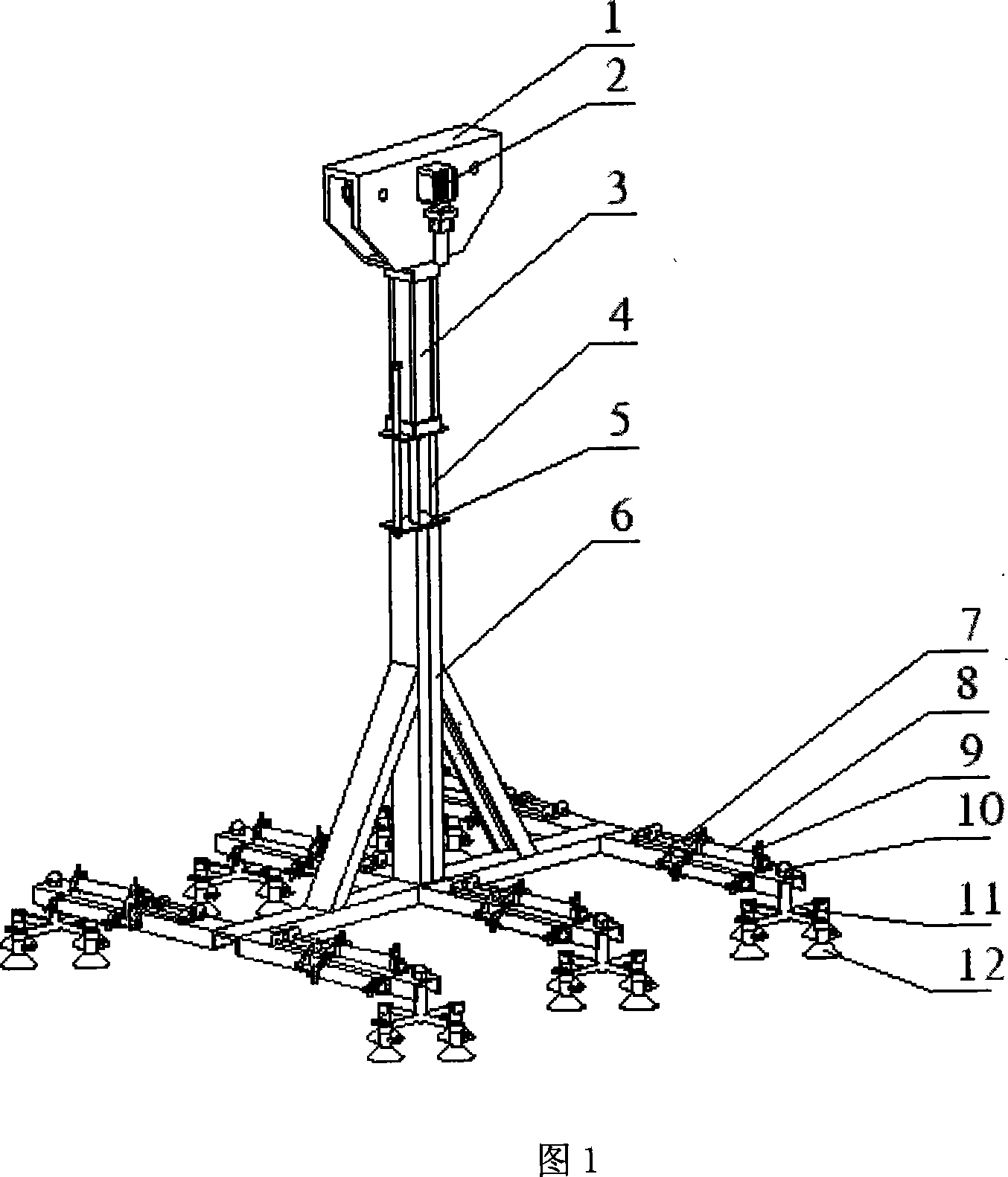
[0013] The present invention will be further described below in conjunction with the accompanying drawings and embodiments.

[0014] In Fig. 1, this tile handling manipulator device is composed of guide rail interface 1, motor 2, upper cylinder 3, connecting rod 4, cylinder joint 5, bracket 6, slide plate 7, bottom cylinder 8, adjustable joint 9, ball nut 10, cylinder connecting rod 11, suction cup 12 is formed. Four suction cups 12 are fixed together by cylinder connecting rods 11 to form a group, and are fixed on the bracket 6 by ball nuts 10. The bottoms of the three bottom cylinders 8 are fixed on the bracket 6 by hexagon socket screws, and the pistons are connected by slide plates 7. Together, the cylinder in the middle has gas input and output, and the piston can move back and forth, thereby driving the movement of the pistons on both sides. The cylinders on both sides are connected to the suction cups through a one-to-two joint. pressure, so that the tiles can be adsor...


PUM


Abstract

The present invention discloses one kind of ceramic tile transporting manipulator, and aims at providing ceramic tile transporting tool with low cost and high safety. The ceramic tile transporting manipulator has the structure including a support, an upper cylinder connected through a link rod with the support, a track connected to the upper cylinder, a motor on the track, and a suction cup unit in the lower part of the support.

Description

technical field [0001] The invention relates to a tile handling manipulator, in particular to a tile handling manipulator which uses the movement of a cylinder piston to generate pressure on a sucker. Background technique [0002] In modern life, gas suction cups have a wide range of applications. Such as high-rise cleaning robots, negative pressure air suction cups, etc. Ceramic tiles are widely used in our home life, especially in the decoration industry, but the fragile characteristics of ceramic tiles cause many problems in the transportation process, and now the short-distance transportation in the production process is mainly carried out manually or delivered form, but the capital investment and safety of the conveyor belt are not ideal, and manual handling is time-consuming and expensive. And the tile handling device on the market is only an auxiliary tool for manual handling, and cannot fundamentally solve the problems existing in the tile handling process. Conte...

Claims


Application Information

Patent Timeline
Patent Type & Authority Applications(China)
IPC IPC(8): B25J3/00B25J15/06
Inventor 于复生沈孝芹李琦李巍郭梅静
Owner 于复生
Why Eureka
Try Eureka