

Thermal printer and method of controlling the same
A printing machine, thermal technology, applied in printing, typewriter, printing device, etc., can solve the problems of long time, consumption and so on
- Summary
- Abstract
- Description
- Claims
- Application Information
AI Technical Summary
Problems solved by technology
Method used
Image

Examples
no. 1 example
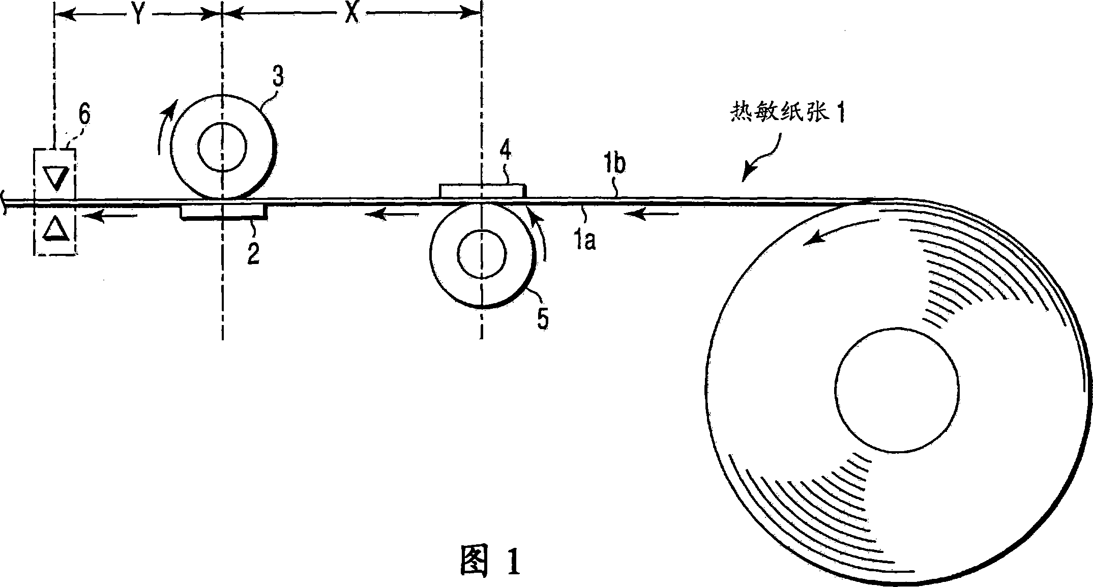
[0048] Hereinafter, a first embodiment according to the present invention will be described with reference to the drawings. First, FIG. 1 shows the structure of the main part.
[0049] Reference numeral 1 denotes thermal paper. The two surfaces (namely, the first surface (referred to as the front side) 1a and the second surface (referred to as the back side) 1b) of the thermal paper 1 having a positive and negative relationship are respectively provided with thermosensitive layers. The near-end side of the thermal paper 1 is rolled up in such a way that the front face 1a becomes the inside, and is fed into the far-end side in the direction indicated by the arrow in the drawing by a paper feeding device 22 described later. The heat-sensitive layer is formed of a material whose color changes to, for example, black or red when heated to a predetermined temperature or higher.
[0050] A first thermal head 2 in contact with the front side 1a of the thermal paper 1 and a second thermal ...
no. 2 example
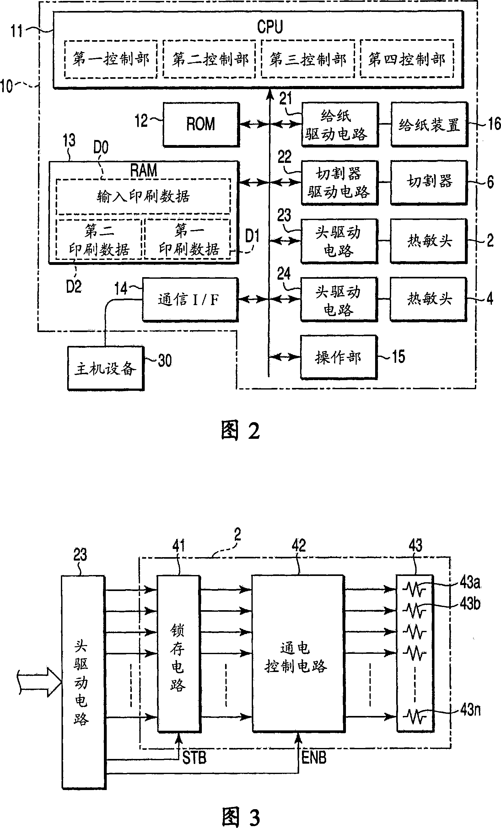
[0102] A second embodiment according to the present invention will now be explained with reference to the drawings. The basic structure of this embodiment is the same as that shown in FIG. 1, so its description is omitted. FIG. 11 shows the control circuit of the thermal printer main body 10.
[0103] The CPU 11 has the following devices (11) to (14) as main functional components.
[0104] (11) A search unit for searching the print data Dm corresponding to the pre-recorded keyword from the print data D0 input from the external host device 30. This keyword is at least one item included in the print data to be printed on one side of the thermal paper 1.
[0105] (12) A recording unit for recording keywords based on the operation of the operation unit 15.
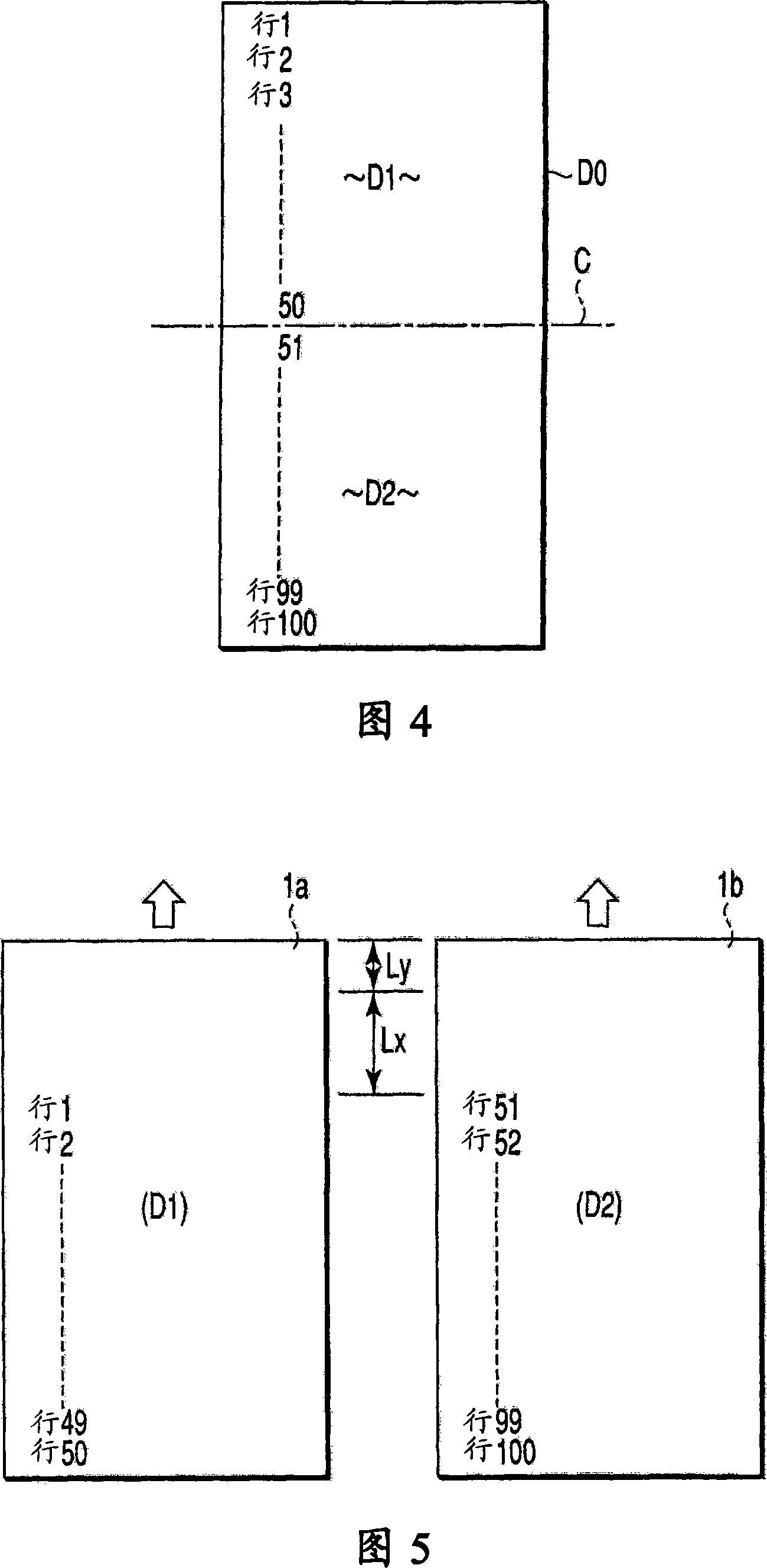
[0106] (13) A first control unit for dividing the input print data D0 into the first print data D1 for the first thermal head 2 that includes the retrieved print data Dm and the one that does not include the retrieved print data D...
no. 3 example
[0125] A third embodiment according to the present invention will now be explained with reference to the drawings. The basic structure is the same as that shown in Figure 1.
[0126] In addition, as shown in FIGS. 20 and 21, the first thermal head 2 has operation ineffective areas of predetermined widths T1a and T1b (when printing, it is impossible to perform sufficient heating at one end and the other end thereof), and has two The operation valid area T1 between the operation invalid areas. The second thermal head 4 also has operation ineffective areas of predetermined widths T2a and T2b (when printing, it is impossible to perform sufficient heating at one end and the other end thereof), and has an operation effective area between the two operation ineffective areas T2.
[0127] FIG. 17 shows the control circuit of the thermal printer main body 10.
[0128] That is, the detection unit 17 is connected to the CPU 11. The detection unit 17 optically or mechanically detects the width...
PUM
 Abstract
Description
Claims
Application Information