
Bolt-on radial bleed manifold

A technology of exhaust pipe and discharge channel, which is applied in the field of rotating machinery, can solve the problems of thermal response mismatch and damage load path, etc., and achieve the effect of improving thermal response, improving gravity sag, and tight clearance

Inactive Publication Date: 2007-12-05
GENERAL ELECTRIC CO
View PDF1 Cites 6 Cited by
  • Summary
  • Abstract
  • Description
  • Claims
  • Application Information

AI Technical Summary

Problems solved by technology

This current compressor discharge duct construction also adds to the challenge of good casing design as it disrupts the otherwise smooth load path, creating unsupported casing wall sections that cause the so-called "springboard" effect, limiting the location and into the resultant load of the casing, and creates a thermal response mismatch between the rotor and casing

Method used


Image

  • Bolt-on radial bleed manifold
  • Bolt-on radial bleed manifold

Examples


Embodiment Construction

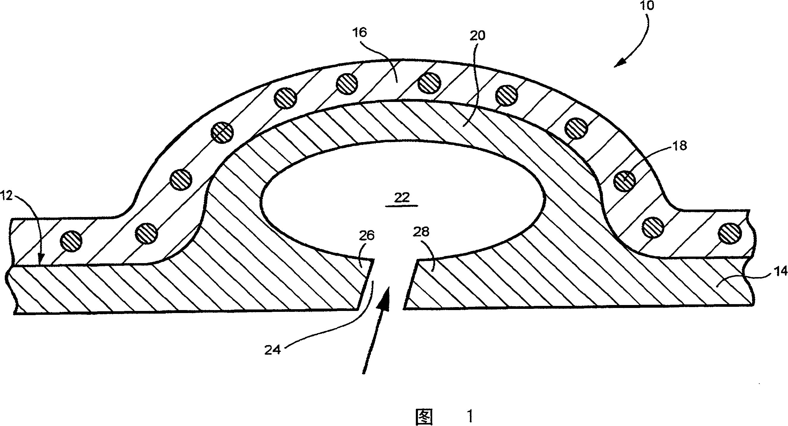
[0014] FIG. 1 shows a conventional discharge slot and tube arrangement 10 for a compressor 12 . The compressor casing 14 is formed from two half-shell parts joined by bolts 18 or the like along vertical flanges. The tube 20 is integral with the housing wall and includes a plenum chamber 22 and a continuous annular inlet slot 24 connecting the plenum chamber 22 with the internal flow path of the compressor 12 . Note that the unsupported edge portions 26 , 28 of the housing 14 are on either side of the slit 24 . These unsupported casing sections can deflect inwardly and / or outwardly, causing what is commonly known as a "springboard" effect that adversely affects the ability to control the tight flow path clearance between the compressor blades (not shown) and the casing wall . It should also be noted that the bolt hole pattern for the bolts 18 adjacent to the plenum chamber 22 is radially spaced outward from the plenum chamber and the inlet slot 24 which adversely affects the ...


PUM


Abstract

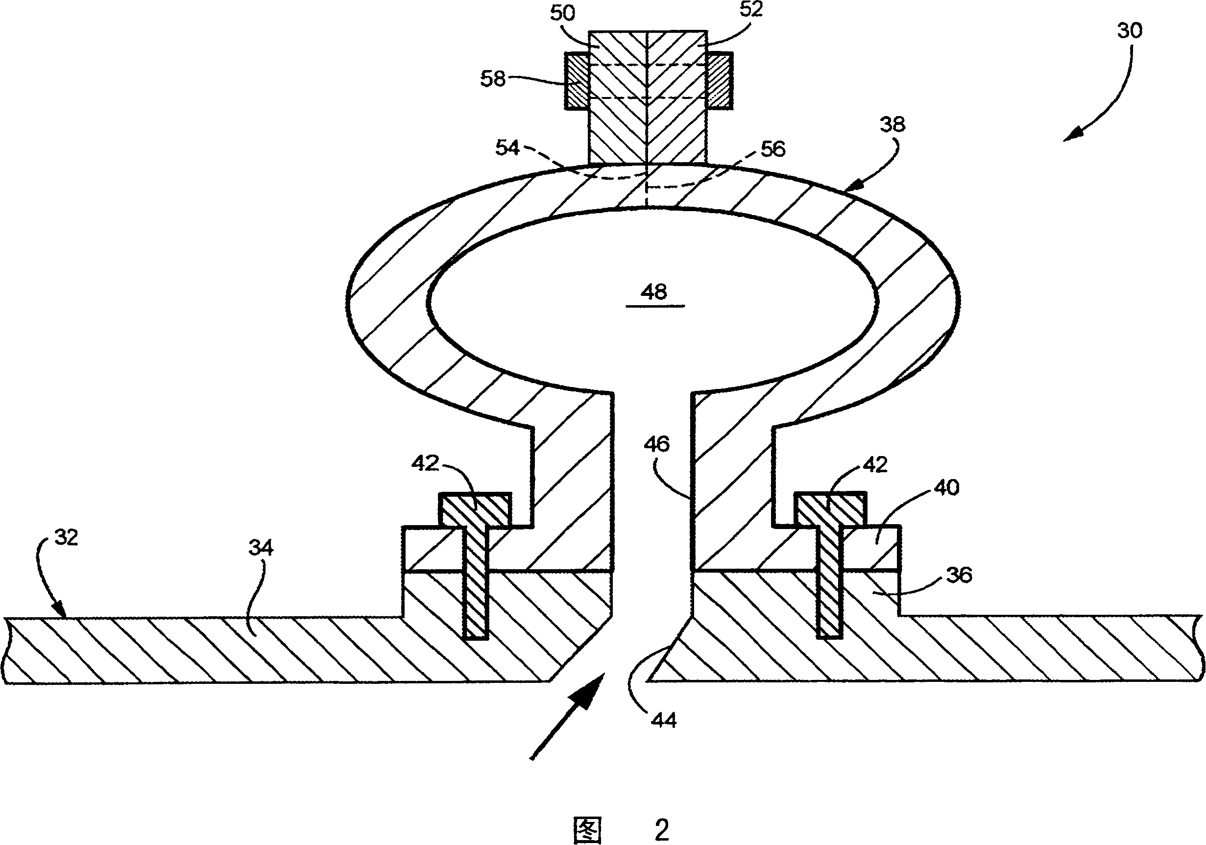
A compressor radial bleed manifold and compressor case assembly includes a compressor case (34) having one or more bleed flow exit passages (44) therein; and a discrete bleed manifold (38) mounted on the compressor case and having one or more inlet passages (46) extending radially between a manifold plenum (48) and the one or more exit passages (44) in the mounting boss for bleeding compressor air into the manifold plenum.

Description

technical field [0001] The present invention relates to rotating machinery technology, and more particularly to a separate compressor discharge pipe which can be secured to an associated compressor casing. Background technique [0002] Reducing the radial clearance between the rotating compressor blades and the compressor casing in axial flow industrial gas turbines is critical to improving performance. Current industrial gas turbine compressor exhaust pipes are integral to the basic compressor casing structure. In other words, current industrial turbine housing design principles integrate the exhaust pipe with the compressor housing. However, this configuration is not conducive to reducing compressor clearances because a separate shroud or casing is required to carry the engine loads and maintain a tight flow path around the clearances. Typically, such tubes include axially extending and opposed vertical flanges, opposed duct sections connected by a plurality of transvers...

Claims


Application Information

Patent Timeline
Patent Type & Authority Applications(China)
IPC IPC(8): F04D29/52F02C7/00
CPCF02C6/08F01D9/026F01D17/105F04D29/545
Inventor N·F·马丁J·E·森库拉
Owner GENERAL ELECTRIC CO
Learn More