
Welding workbench capable of precisely controlling gap and precise gap control method

A workbench and gap technology, applied in welding equipment, manufacturing tools, auxiliary welding equipment, etc., can solve problems affecting the accuracy of welding fixtures, weld pores, and affect welding joints, etc., to achieve precise gap control, improve welding efficiency, The effect of reducing tedious work

Pending Publication Date: 2021-06-25
XIANGTAN UNIV
View PDF7 Cites 0 Cited by
  • Summary
  • Abstract
  • Description
  • Claims
  • Application Information

AI Technical Summary

Problems solved by technology

And this gap distance is usually after manual measurement, and then artificially adjust the gap between the two parts to be welded. If the above-mentioned operation of manually measuring the gap value is repeated before each welding, it will bring great inconvenience. Not only will the welding operation time be greatly increased, thereby reducing the overall work efficiency of the welding process
Moreover, the welding operation is repetitive and cumbersome, and the uncertainty of the welding worker's operation technology and work mood makes the manual measurement of the gap value between the parts to be welded have large errors, and even causes the gap between the left and right sides of the welding direction to be unequal , reduce the accuracy of the gap value of the weldment to be welded, and affect the accuracy of the welding tool
[0003] On the other hand, the gap value between the parts to be welded also affects the quality of the welded joint, especially when performing butt welding on medium and thick plates, when the molten metal in the molten pool flows violently, air will be drawn into the molten pool, if When there is no gap or the gap is too small, the gas in the molten pool may not be discharged in time during the cooling of the molten metal, which will cause pores in the weld, which will affect the quality and mechanical properties of the welded joint

Method used


Image

  • Welding workbench capable of precisely controlling gap and precise gap control method
  • Welding workbench capable of precisely controlling gap and precise gap control method
  • Welding workbench capable of precisely controlling gap and precise gap control method

Examples


Embodiment Construction

[0023] The present invention will be further described below in conjunction with the accompanying drawings.

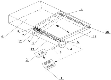
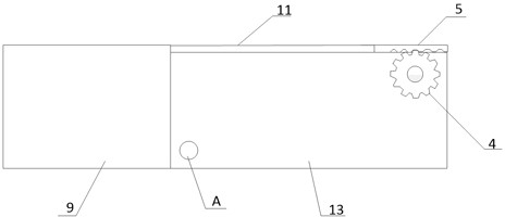
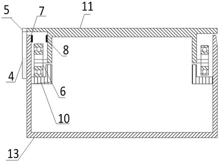
[0024] Such as Figure 1-4 As shown, a welding workbench with precise gap control includes a fixed table 9, a fixed seat 13, a shielding gas flow channel 12, a sliding table 11, a traveling mechanism, a displacement sensor and a control system 1.

[0025] The fixed table 9 is fixedly mounted on one end of the fixed seat 13, the slide table 11 is supported on the fixed seat 13, and a traveling mechanism is arranged between the slide table 11 and the fixed seat 13. Described walking mechanism comprises motor 1, shaft coupling 3, gear 4, rack 5 and guiding mechanism; Described gear 4 is installed on the holder 13, and rack 5 is fixedly installed on the slide table 11, and gear 4 and The rack 5 meshes. The output shaft of the motor 2 is connected with the gear 4 through a shaft coupling 3 . A guiding mechanism is arranged between the slide table 11 and the fixed seat 13...


PUM


Abstract

The invention discloses a welding workbench capable of precisely controlling a gap and a precise gap control method. The workbench comprises a fixed table, a fixed seat, a protective gas flowing channel, a sliding table, a travelling mechanism, a displacement sensor and a control system; the fixed table is fixedly installed at one end of the fixed seat, the sliding table is supported on the fixed seat, and the travelling mechanism is arranged between the sliding table and the fixed seat and can make the sliding table close to or away from the fixed table; the displacement sensor is arranged between the sliding table and the fixed seat, the protective gas flowing channel is arranged on the fixed seat, and the protective gas flowing channel is located at one end, facing the sliding table, of the fixed table; and the displacement sensor and the travelling mechanism are connected with the control system. The welding workbench is simple in structure and convenient to operate; repeated tedious work by workers can be reduced, errors caused by human factors are reduced, the workpiece mounting time can be effectively shortened, and the welding efficiency is improved; and the gap control is precise.

Description

technical field [0001] The invention belongs to the field of welding technology, and in particular relates to a welding workbench with precise gap control and a precise gap control method. Background technique [0002] Welding is one of the main joining methods of metal materials in industrial production. It is widely used in many industries and manufacturing fields such as aerospace, ships, vehicle transportation and pressure vessels, and has a very large application market. With the development of welding technology, various advanced welding methods have emerged, such as MIG / MAG arc welding, TIG welding, laser welding and hybrid welding, etc., gradually replacing traditional manual welding and improving welding efficiency. In the actual welding process, due to the needs of welding operations, or in order to maximize the advantages of related welding methods, when welding in the form of butt joints, especially for butt welding of medium and thick plates, it is necessary to ...

Claims


Application Information

Patent Timeline
Patent Type & Authority Applications(China)
IPC IPC(8): B23K37/04B23K37/047
CPCB23K37/04B23K37/047
Inventor 刘金刚郑剑云姜胜强傅兵赵又红戴师羽彭晓宇
Owner XIANGTAN UNIV
Learn More