Monitoring apparatus

A technology of monitoring device and communication module, which is applied in the direction of selection device, current supply device, telemetry/remote control selection device, etc., which can solve problems such as difficult automatic recovery, abnormal communication monitoring system operation obstacles, difficulty in obtaining router data, etc., and achieves reduction The effect of the lapsed time

A technology of monitoring device and communication module, which is applied in the direction of selection device, current supply device, telemetry/remote control selection device, etc., which can solve problems such as difficult automatic recovery, abnormal communication monitoring system operation obstacles, difficulty in obtaining router data, etc., and achieves reduction The effect of the lapsed time

CN101083698AInactive Publication Date: 2007-12-05HITACHI IND EQUIP SYST CO LTD

Image

  • Monitoring apparatus
  • Monitoring apparatus
  • Monitoring apparatus

Examples


Embodiment Construction

[0025] The best mode for carrying out the present invention will be described.

[0026] Hereinafter, an embodiment of the monitoring device of the present invention will be described with reference to the drawings.

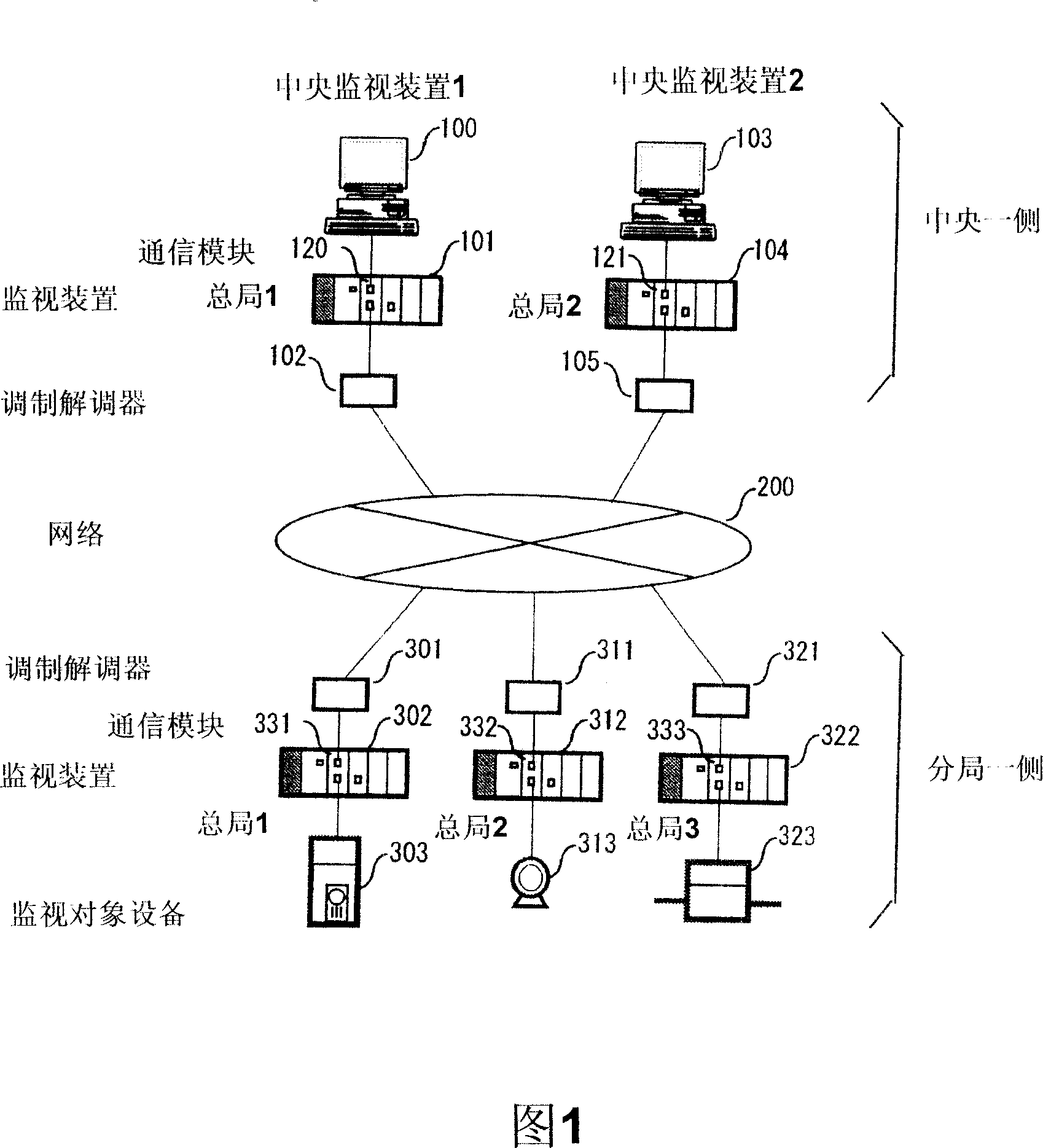
[0027] Examples will be described. The overall configuration of the monitoring system of this embodiment is shown in FIG. 1 . Central monitoring devices 100, 103, monitoring devices 101, 104 at the central office side, and modems 102, 105 are installed on the central side. Modems 301, 311, and 321 are installed on the branch office side, and monitoring devices 302, 312, and 322 on the branch office side monitor and remotely control monitoring target devices 303, 313, and 323.

[0028] In the network 200, since the multi-channel communication by TCP / IP etc. is used, the monitoring system of the central side can be installed and connected in several places. In this embodiment, two locations of the central monitoring device 1 (100) and the central monitoring devic...


PUM


Abstract

A monitoring apparatus that captures data in a router into a monitoring apparatus to cope with a communication abnormality in a monitoring system that uses the router, a modem, and a network. The monitoring apparatus comprises input modules 343, 345 for being input with a signal from a monitored object 303; a CPU module 341 for processing the signal from the input modules 343, 345; a communication module 342; a data bus 352; and a power module 340. The communication module has two connectors 204, 206 or more each connected to the network; a connection terminal connected to a power supply buss 351; a connection terminal connected to the data bus 352; a memory; and a CPU.

Description

technical field [0001] The present invention relates to a monitoring device, and more particularly relates to a technology for monitoring water supply and distribution facilities of sewers and sewers, industrial production equipment and sales data collection equipment. Background technique [0002] In the monitoring system of the prior art, a monitoring device is installed in a central monitoring room, and a monitoring device that transmits data on the field side to the central monitoring room is installed on the field side where equipment to be monitored is installed. A dedicated line or cable TV line is connected to form a monitoring system. In these communications, a router or a modem is connected to the monitoring device, and communication is performed between the monitoring devices at both ends of the communication line (for example, refer to Japanese Patent Application Laid-Open No. 10-327259). [0003] In the related art monitoring system, data on whether the communi...

Claims


Application Information

Patent Timeline
05 Dec 2007
Publication
CN101083698A
IPC
H04M11/00; H04L29/00; H04M19/00; H04Q9/00; H04L69/40
CPC
H04L43/0817
Inventors
高桥一郎; 黑川靖午